Thrust bearing and combo bearing

a technology applied in the field of thrust bearings and combo bearings, can solve the problems of increasing costs, increasing the volume of bearing systems on rotators, and rotators that require high durability, so as to improve the vulnerability to axial loads, increase durability, and simplify the effect of structur

Active Publication Date: 2014-07-17
KOREA INST OF MASCH & MATERIALS
View PDF17 Cites 10 Cited by
  • Summary
  • Abstract
  • Description
  • Claims
  • Application Information

AI Technical Summary

Benefits of technology

[0039]According to an exemplary embodiment of the present invention, by supporting the top foils of a thrust bearing with a material formed by pressing metal having constant density, there is a large effect with which it is possible to improve the problem of vulnerability to axial loads and considerably increase durability in comparison to the related art, by making a thin plate function as a damper in the existing air foil thrust bearings. Further, since there is no need to manufacture a bump foil, unlike the existing air foil thrust bearings, there is the effect that the structure is simplified and manufacturing is easy, and accordingly, the present invention can be easily used for small rotators, such that there is a large effect that it is possible to increase the applicability in comparison to the related art.
[0040]The details are as follows. In a device in which a rotary shaft equipped with parts such as a compressor and turbine impellers, including a gas microturbine, rotates at a high speed, axial load and vibration are serious problems. The existing air foil thrust bearings have a problem in that they cannot be applied to the device because they are vulnerable to axial loads, as described above. However, according to an exemplary embodiment of the present invention, there are the advantages that a structure can be easily manufactured in a simple structure while the problems of the related art are eliminated, the size and weight can be reduced, the costs for manufacturing and maintaining are reduced, and it can be used under high-temperature environments with high durability, so it can be used for the device without a problem.
[0041]According to another exemplary embodiment of the present invention, for a rotator having a radial bearing and a thrust bearing in the related art, the combo bearing of the present invention that can achieve the functions of a radial bearing and a thrust bearing as a single part is provided, such that there is the effect that it is possible to reduce the length of a rotator by as much as the length is increased for ensuring spaces for two different types of bearings in the related art. Obviously, as the length of a rotator is minimized, there is also the effect that the volume of the entire system can be reduced. According to the present invention, above all, the length of a rotator is reduced and the critical speed of a rotator in a bending mode increases, such that there is also the effect that it is possible to increase the range of operation speed in which the rotator can stably operate.
[0042]Further, by supporting the top foils of a bearing with a material formed by pressing metal having constant density, there is a large effect that it is possible to improve the problem of vulnerability to loads and increase durability considerably in comparison to the related art, by making a thin plate function as a damper in the existing air foil bearings. Further, according to the present invention, since there is no need to manufacture a bump foil, unlike the existing air foil bearings, there is the effect that the structure is simplified and manufacturing is easy, and accordingly, the present invention can be easily used for small rotators, such that there is a large effect that it is possible to increase the applicability in comparison to the related art. That is, by using a metal mesh damper, there are the advantages that a structure can be easily manufactured in a simple structure while the problems of the related art are eliminated, the size and the weight can be reduced, the costs for manufacturing and maintaining are reduced, and it can be used under high-temperature environments with high durability.
[0043]Further, according to an exemplary embodiment of the present invention, there is a large effect that it is possible to solve the problem that it is difficult to dispose bearings due to the structure in which the existing bearings cannot be fitted from any one side, in an impeller-rotary shaft-integrated rotator in which impellers and a rotary shaft are integrated. That is, the bearing of the present invention can be divided, such that there is the effect that the bearing can be combined at any desired position no matter how complicated the shape of a rotator is, in addition to an impeller-rotary shaft-integrated rotator.

Problems solved by technology

Further, the rotators require high durability to prevent bearings from being damaged due to axial loads.
Further, recently, a divisional type of power generation technology has been more commercialized all over the world due to an increase in costs for initial installations because the cost per kilowatt for transmitting power is high in centralized systems, and there is a need for inexpensive basic structures to distribute generated power to consumers.
However, there is a problem in that the bearing systems on rotators necessarily increase in volume, because the bearings are separate parts.
The larger the volume of the bearing systems, the larger the length of rotators becomes, and accordingly, the primary bending mode (critical speed) of the rotators is lowered, which causes a problem in that the stability of small rotators is considerably decreased during high-speed rotation.
Further, in the process of separately manufacturing the two types of bearings and assembling them, a specific back plate for mounting the thrust bearing is needed and there is a need of a process for fitting the degree of precision in assembling, thereby causing the assembly process to be complicated.
In addition, as described above, in order to satisfy the conditions of non-contact type and no oil supply, it is difficult to use ball bearings and sliding bearings, which are widely used, and it is required to use air foil bearings and electromagnet bearings, but those bearings have the following problems.
The air foil bearings are practically difficult to use, particularly for a thrust bearing, due to very poor structural durability, and there is a limit in reducing the size of a bump foil.
The electromagnetic bearings have a problem in that the configuration of the devices is complicated and expensive, so they are not economical.
Further, the following problems have been generated with the progress of studies for improving the shapes of small rotators such as those used in the gas microturbines described above. FIGS. 8A and 8B are views showing the arrangement of bearings on a rotary shaft coupled with impellers in the related art.
However, in the rotator having this configuration, imbalance and bending between the rotary shaft rotating at a high speed and the parts on the end of the rotary shaft are problematic.
However, with design and development of a rotator configured by integrating a rotary shaft and impellers due to the problem of imbalance that is generated when a rotary shaft and impellers are combined, there is another problem in that it is very difficult to combine the bearings of the related art with the integrated impellers and rotary shaft.

Method used


Image

  • Thrust bearing and combo bearing
  • Thrust bearing and combo bearing
  • Thrust bearing and combo bearing

Examples


Embodiment Construction

[0052]A thrust bearing and a combo bearing according to the present invention which have the configurations described above will be described hereafter with reference to the accompanying drawings.

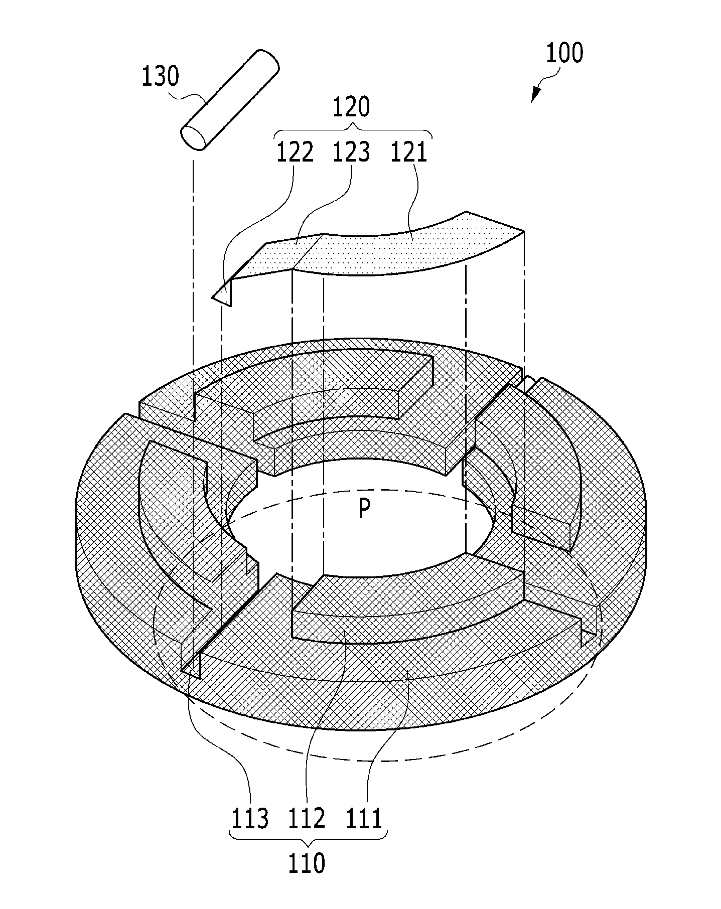
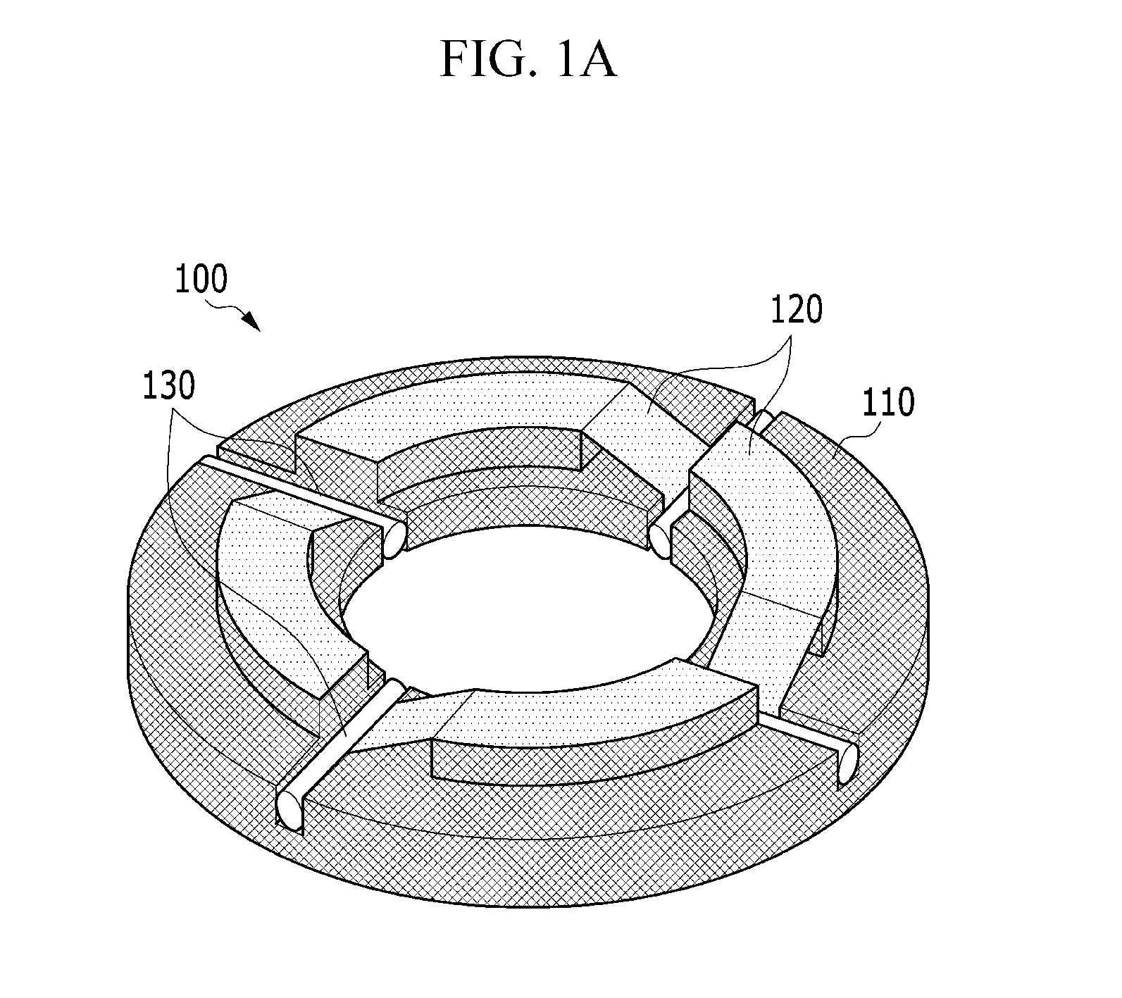
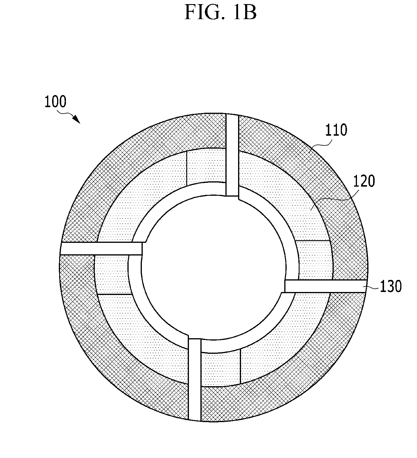
[0053]FIGS. 1A, 1B, and 2 are a perspective view, a plan view, and an exploded perspective view, respectively, of a metal mesh foil thrust bearing according to a first exemplary embodiment of the present invention.

[0054]Referring to FIGS. 1A, 1B, and 2, a metal mesh foil thrust bearing 100 according to the present exemplary embodiment basically includes a damper body 110 and thrust top foils 120.

[0055]The damper body 110, as shown in FIG. 2, has a body part 111, protrusions 112, and grooves 113. The protrusions 112 protrude upward with flat tops at some areas on the body part 111, and the grooves 113 are recessed on one side of the body part 111. The damper body 110 may be implemented by circumferentially arranging at least two unit collars P composed of the body part 111, the protrusion 11...


PUM


Abstract

The present disclosure provides a thrust bearing that includes: a damper body including a body part and protrusions axially protruding at predetermined areas on the body part with flat tops; and thrust top foils each having a contact portion that is in surface contact with the tops of the protrusions. The present disclosure provides a combo bearing that includes: a damper body including a body part having a through-hole at the center through which a rotary shaft passes, and protrusions axially protruding at predetermined areas on the body part with flat tops; thrust top foils each having a contact portion that is in surface contact with the tops of the protrusions; and a radial top foil covering the rotary shaft and disposed along the inner side of the through-hole of the damper body.

Description

CROSS-REFERENCE TO RELATED APPLICATION[0001]This application claims priority to and the benefit of Korean Patent Application No. 10-2013-00005024 and 10-2013-0005126 filed in the Korean Intellectual Property Office on Jan. 16, 2013, and Jan. 16, 2013, the entire contents of which are incorporated herein by reference.BACKGROUND OF THE INVENTION[0002](a) Field of the Invention[0003]The present invention relates to a bearing that is mounted on a rotary shaft of a rotator and supports the rotary shaft perpendicular to or in parallel with (axially) the rotary shaft.[0004](b) Description of the Related Art[0005]In parts (a rotary shaft and a moving shaft) that make motions such as rotation or reciprocation, various types of bearings are provided to solve problems such as wear or damage of the parts, noise, and waste of energy due to friction that may be generated in the motions of the parts. The bearing on which loads are applied perpendicular to the rotational axis is called a radial bea...

Claims


Application Information

Patent Timeline
Patent Type & Authority Applications(United States)
IPC IPC(8): F16C17/10F16C33/10F16C17/04
CPCF16C17/10F16C33/101F16C17/042F16C27/02F16C2360/00F16C2360/23
Inventor PARK, CHEOL-HOONCHOI, SANG-KYUHONG, DOO EUYYOON, TAE GWANG
Owner KOREA INST OF MASCH & MATERIALS
Why Eureka
Try Eureka