Method of operating a wind turbine

a wind turbine and turbine blade technology, applied in the direction of wind turbines, non-positive displacement fluid engines, pump control, etc., can solve the problems of increasing drag, reducing the lift of a profile, and not necessarily optimal operation, so as to achieve the effect of further maximising energy

Active Publication Date: 2014-07-17
GE RENEWABLE TECH WIND BV
View PDF4 Cites 11 Cited by
  • Summary
  • Abstract
  • Description
  • Claims
  • Application Information

AI Technical Summary

Benefits of technology

[0038]In accordance with this aspect, contrary to conventional wisdom, the pitch angle of the blades is changed in the sub-nominal zone of operation in order to maximise energy further.

Problems solved by technology

However, in non-steady state (transient) conditions, the operation may not necessarily be optimum.
The separation causes a wake of turbulent flow, which reduces the lift of a profile and increases the drag significantly.
However, in general, regardless of the aerodynamic profile chosen, a trend to increasing lift up until a critical angle of attack and also a rapid increase in drag after a critical angle of attack can be found.
From this, it follows that the torque generated by a rotor blade section may become a rather complicated function of the instantaneous tip speed ratio and the pitch angle of the blade.
Below that pitch angle, stall may occur.
In an even worse scenario, turbulent wind conditions with continuously varying wind speeds might exist.
In such case, the inertia of the rotor does not permit tracking of the wind speed at any time, so the wind turbine will not be operating at maximum Cp unless said wind turbulence decreases.
Wind energy that could be converted into electrical energy is thus being lost.

Method used


Image

  • Method of operating a wind turbine
  • Method of operating a wind turbine
  • Method of operating a wind turbine

Examples


Embodiment Construction

[0045]FIG. 3 illustrates a wind turbine 40 having a rotor with three blades 41, 42 and 43. A nacelle 45 is mounted on wind turbine tower 44. An anemometer 46 is mounted on the nacelle 45. The anemometer 46 may be used to measure wind speed, however because of its location on the nacelle, behind the rotor, the wind speed measured by the anemometer may vary a lot and in general may not be very reliable.

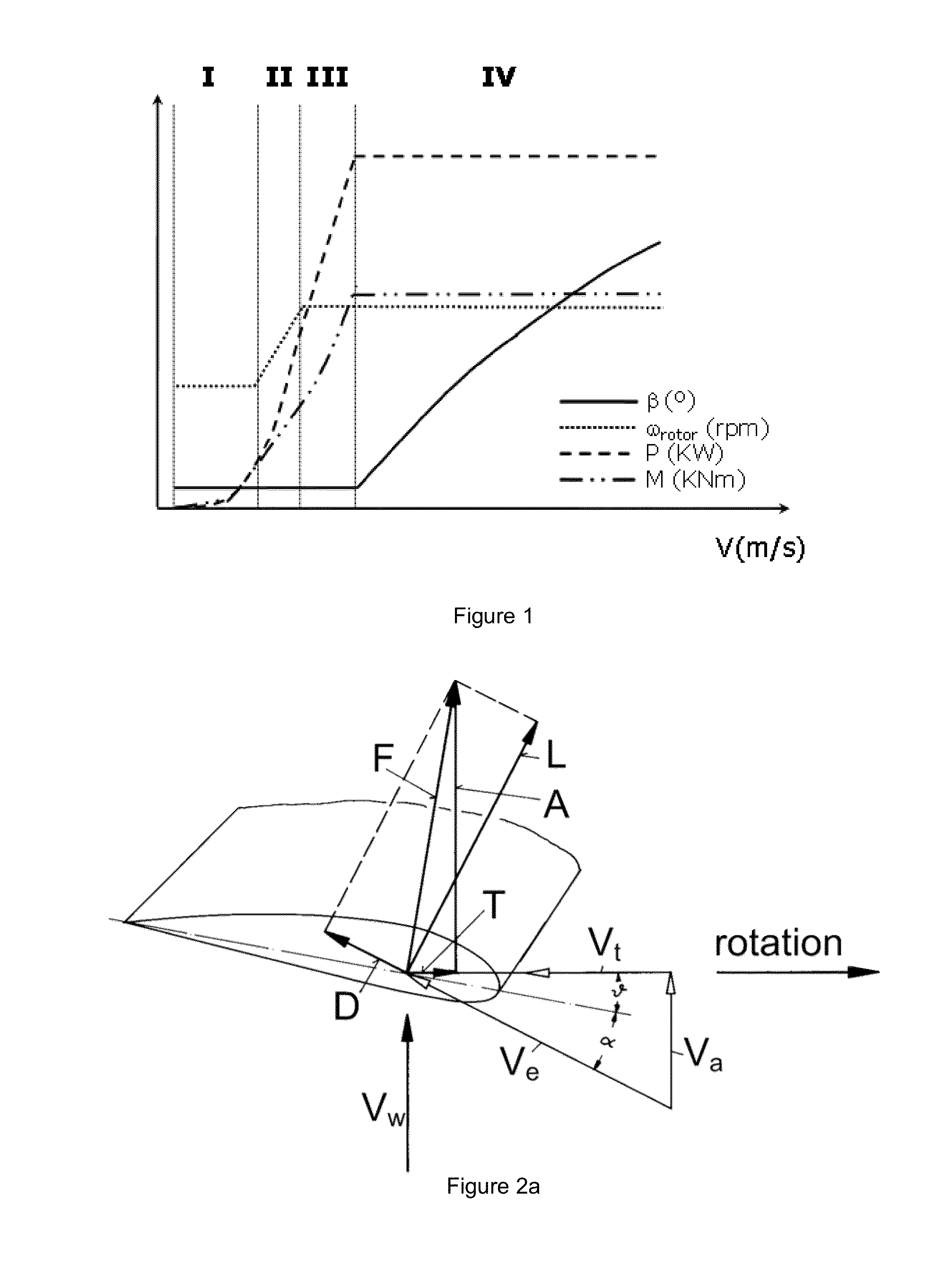
[0046]The wind turbine may have one or more pitch systems to rotate the blades 41, 42, 43 collectively or individually. FIG. 1 represents a typical power curve for a variable speed wind turbine with pitch capability. As mentioned before, above the nominal wind speed, the generator torque and rotor speed are maintained constant even though the wind speed increases. This is achieved by pitching the wind turbine blades, i.e. by rotating the blades along their longitudinal axes and with respect to the hub; by increasing the pitch of the blades, their angle of attack decreases and their cont...


PUM


Abstract

A method of operating a variable speed wind turbine as a function of a wind speed is disclosed. The method comprises following a power curve describing the operation of the wind turbine as a function of wind speed in steady-state conditions. The method further comprises changing the pitch angles of the blades in transient conditions in which the wind turbine cannot follow the power curve in the second operational range.

Description

[0001]This application claims the benefit of European Patent Application 13 382 014.2 filed on Jan. 17, 2013 and U.S. Provisional Patent Application Ser. No. 61 / 802,964 filed on Mar. 18, 2013, which are herein incorporated by reference in their entirety for all purposes.[0002]The present disclosure relates to methods of operating a wind turbine.BACKGROUND ART[0003]Modern wind turbines are commonly used to supply electricity into the electrical grid. Wind turbines of this kind generally comprise a rotor with a rotor hub and a plurality of blades. The rotor is set into rotation under the influence of the wind on the blades. The rotation of the rotor shaft either directly drives the generator rotor (“directly driven”) or through the use of a gearbox.[0004]A variable speed wind turbine may typically be controlled by varying the generator torque and the pitch angle of the blades. As a result, aerodynamic torque, rotor speed and electrical power will vary.[0005]A common prior art control ...

Claims


Application Information

Patent Timeline
Patent Type & Authority Applications(United States)
IPC IPC(8): F03D7/02
CPCF03D7/0276F03D7/0224Y02E10/72
Inventor PINEDA AMO, ISAAC
Owner GE RENEWABLE TECH WIND BV
Why Eureka
Try Eureka