Check patentability & draft patents in minutes with Patsnap Eureka AI!

Anti-Displacement Coil Spring-Type Spine Stabilization Device

Inactive Publication Date: 2014-07-17
PAONAN BIOTECH
View PDF3 Cites 7 Cited by
  • Summary
  • Abstract
  • Description
  • Claims
  • Application Information

AI Technical Summary

Benefits of technology

The present invention provides an anti-displacement coil spring-type spine stabilization device that can be securely fixed on one side of a spine by multiple pedicle screws. The device includes a coil spring member, two connection members, and at least one elastic bar. The elastic bar is axially extended through the coil spring member and securely positioned in sockets of the connection members. The coil spring member is made of a spiral spring wire, which has threads that can be directly screwed on the corresponding spiral grooves of the connection members or elastically engaged with the annular grooves of the connection members. The device prevents the coil spring member from being greatly displaced under radial action force. This secure and cost-effective manufacturing process simplifies the manufacturing process and reduces the manufacturing cost.

Problems solved by technology

It is known that when the intervertebral disc between two vertebras of the spine is damaged to compress the nerve, a patient will feel sore and painful.
However, the metal rod member used in the fusion surgery cannot be elastically bent and tensioned.
As a result, the lesion vertebra is likely to be compressed again to make the patient feel painful.
That is, the spine stabilization device of U.S. Pat. No. 8,080,038 can hardly protect the vertebras from radial action force.
As a result, the lesion vertebra may be further injured.
Therefore, the rod-shaped implant element 1 needs to be mechanically processed four times. This complicates the manufacturing process and leads to increase of cost.
In this case, it is more difficult to process the rod-shaped implant element 1.
Similarly, the first sprint member 2 needs to be mechanically processed many times. This also complicates the manufacturing process and leads to increase of cost and needs to be improved.
This is unsuitable for a patient with injured spine due to compression.
That is, neither of the above two patents can effectively support the injured spine.

Method used


Image

  • Anti-Displacement Coil Spring-Type Spine Stabilization Device
  • Anti-Displacement Coil Spring-Type Spine Stabilization Device
  • Anti-Displacement Coil Spring-Type Spine Stabilization Device

Examples


Embodiment Construction

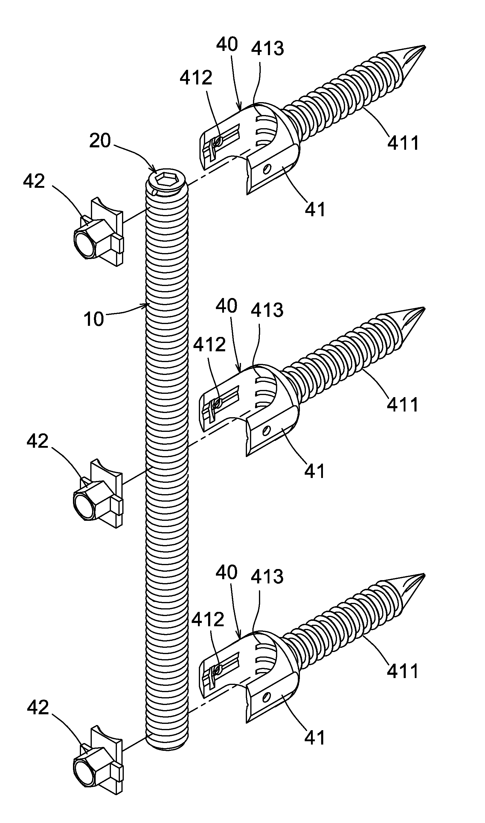
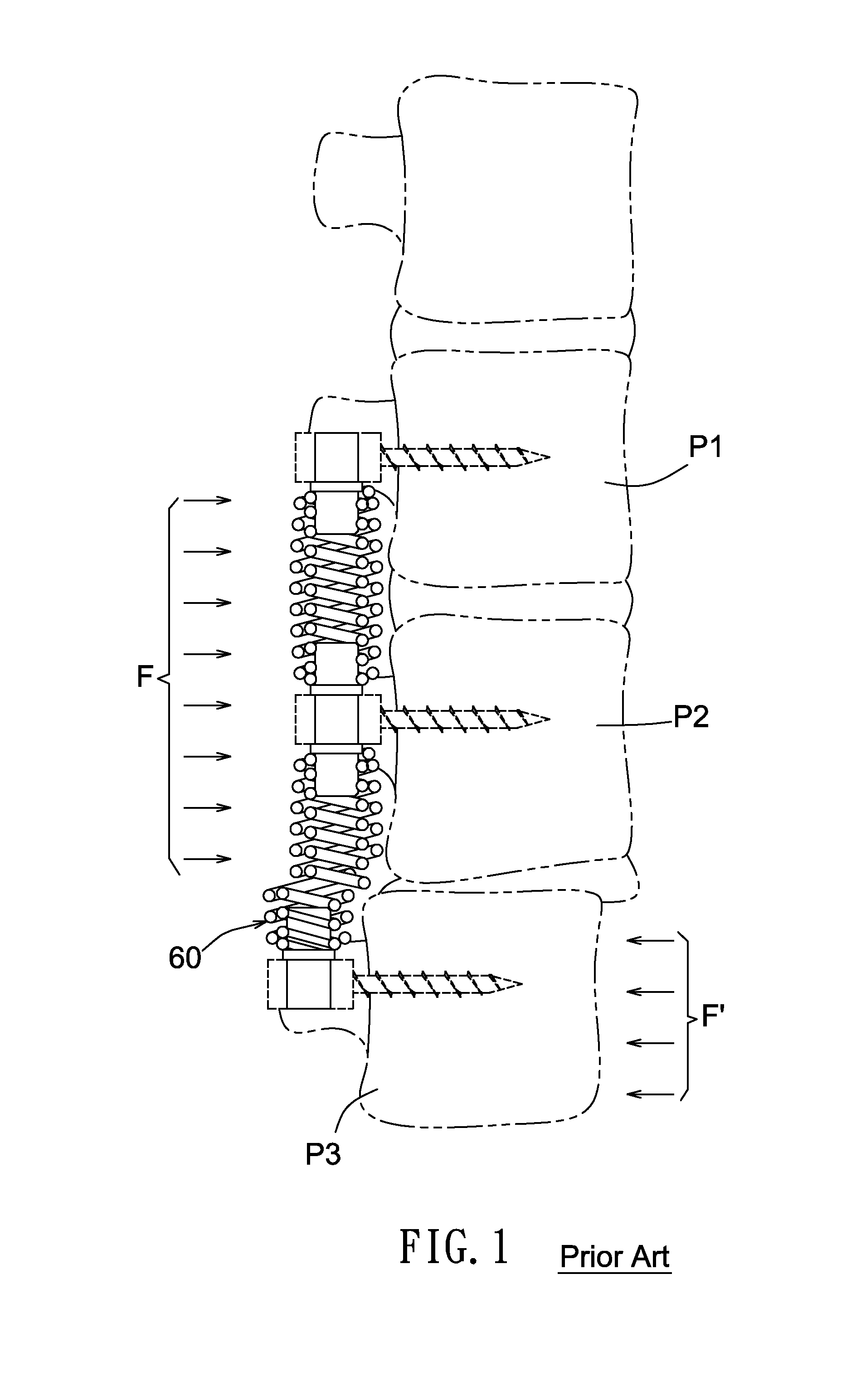
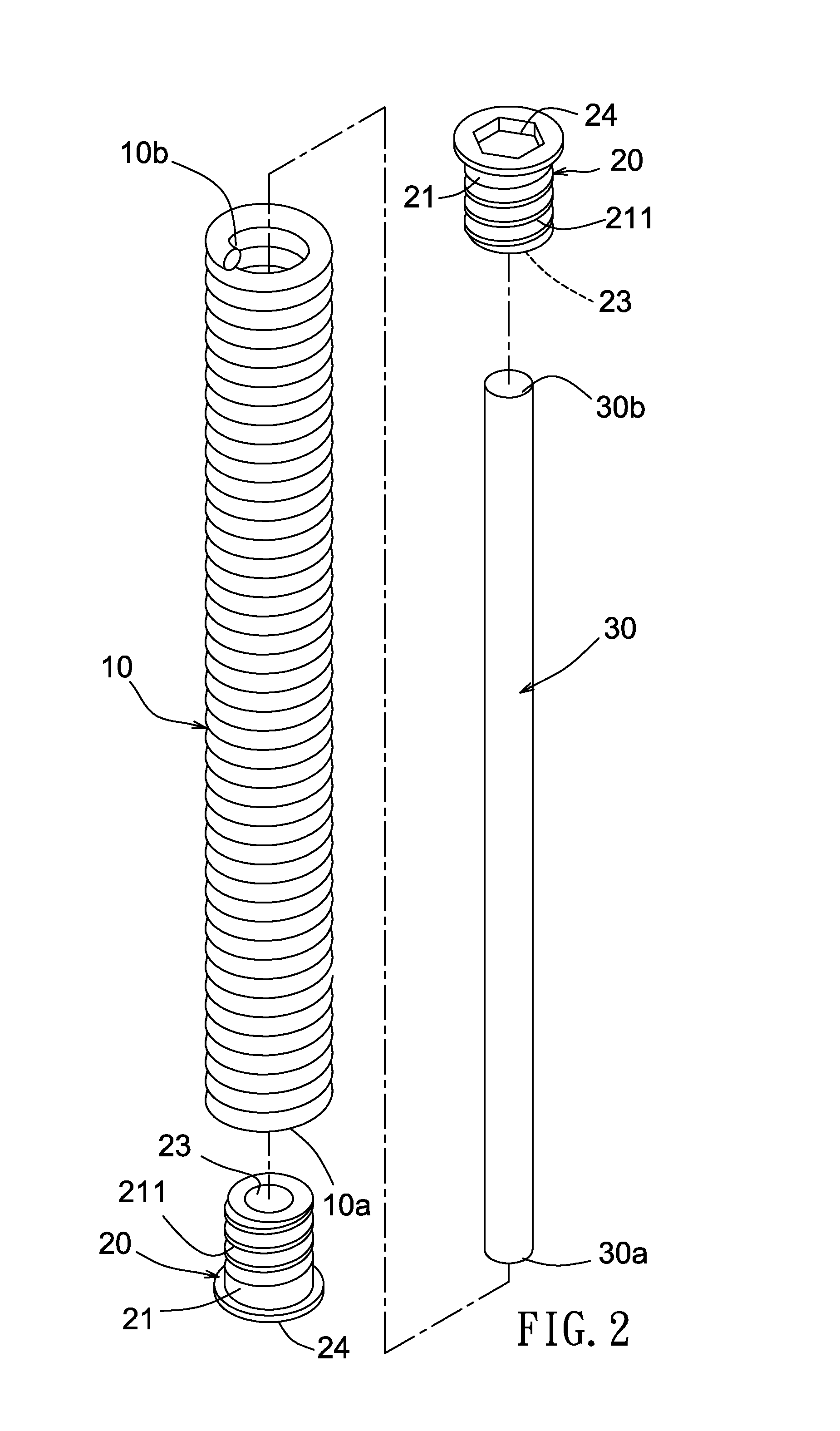
[0045]Please refer to FIGS. 2 to 7. The anti-displacement coil spring-type spine stabilization device of the present invention can be securely fixed on one side of a spine 50 by multiple pedicle screws 40. The spine stabilization device of the present invention includes a coil spring member 10. Two connection members 20 are respectively secured to two ends of the coil spring member 10. An elastic bar 30 is disposed in the coil spring member 10 to axially extend through the coil spring member 10 between the two connection members 20.

[0046]The coil spring member 10 of the spine stabilization device is made of a spiral spring wire having multiple continuous loops. The coil spring member 10 has the form of an elongated bar. Each connection member 20 has a connection section 21. The connection sections 21 are securely connected with two ends 10a, 10b of the coil spring member 10. The opposite end faces of the two connection members 20 are respectively formed with two axially extending so...


PUM


Abstract

An anti-displacement coil spring-type spine stabilization device includes: a coil spring member made of a spiral spring wire having multiple continuous loops, the coil spring member having the form of an elongated bar; two connection members securely connected with two ends of the coil spring member, opposite end faces of the two connection members being respectively formed with two axially extending sockets; and at least one elastic bar disposed in the coil spring member and axially extending through the coil spring member with two ends of the elastic bar respectively extending into the sockets of the connection members. The coil spring member is made of the spiral spring wire so that two ends of the coil spring member are naturally formed with threads, which can be directly screwed on the connection members without further mechanically processing. This simplifies the manufacturing process to lower the manufacturing cost.

Description

RELATED APPLICATION[0001]This application claims the benefit of a Taiwanese patent application, 102200771, filed on Jan. 11, 2013, the specification of which is incorporated here by this reference.BACKGROUND OF THE INVENTION[0002]1. Field of the Invention[0003]The present invention relates generally to an anti-displacement coil spring-type spine stabilization device, and more particularly to a spine stabilization device including a coil spring member made of a spiral spring wire having multiple continuous loops. The coil spring member has the form of an elongated bar. Two connection members are locked on or elastically latched with two ends of the coil spring member. Opposite end faces of the two connection members are respectively formed with two sockets. At least one elastic bar is disposed in the coil spring member and axially extends through the coil spring member with two ends of the elastic bar respectively extending into the sockets of the connection members.[0004]2. Descript...

Claims


Application Information

Patent Timeline
IPC IPC(8): A61B17/70
CPCA61B17/7028A61B17/7029A61B17/7031
Inventor YEH, CHUNG-CHUN
Owner PAONAN BIOTECH
Features
  • R&D
  • Intellectual Property
  • Life Sciences
  • Materials
  • Tech Scout
  • Unparalleled Data Quality
  • Higher Quality Content
  • 60% Fewer Hallucinations
Learn More