Inspecting device monitoring system

a monitoring system and inspection device technology, applied in the field of monitoring systems, can solve the problems of poor production efficiency of operators engaged in such work, low frequency with which defective products are detected by the inspection device, and reducing productivity, so as to achieve the effect of increasing production efficiency

Active Publication Date: 2014-07-17
CKD
View PDF36 Cites 10 Cited by
  • Summary
  • Abstract
  • Description
  • Claims
  • Application Information

AI Technical Summary

Benefits of technology

[0024]As a result, only the operator that has selected the task item displayed on the mobile terminal will perform the checking task for that task item, thereby making it possible to prevent the occurrence of problems such as a plurality of operators, who have received identical information, all performing the same checking task at the same time, even when there is a plurality of operators who possess mobile terminals.
[0025]Additionally, because the structure is one wherein the operator is able to select, on the operator side, the task that he or she is to perform, when compared to a structure wherein an operator for performing a specific task is designated by the system side, it is less likely that there will be problems such as an operator becoming idle or another individual operator being given multiple tasks simultaneously.
[0026]The result is the ability to perform monitoring of inspecting devices by a plurality of operators efficiently, which, by extension, enables an increase in production efficiency. This is especially true when monitoring a plurality of inspecting devices.

Problems solved by technology

Because of this, it is necessary to stop the production line while the operator goes to the inspecting device or the central controlling device, which may lead to a remarkable reduction in productivity.
In response, one may consider having an operator remain constantly at the inspecting device or central controlling device, and may consider performing periodic monitoring, but, when viewed as a whole, the frequency with which defective products are detected by the inspecting devices is certainly not high, so having an operator engaged in such work has poor production efficiency from the perspective of personnel as well.

Method used


Image

  • Inspecting device monitoring system
  • Inspecting device monitoring system
  • Inspecting device monitoring system

Examples


Embodiment Construction

[0058]One or more embodiments of the claimed invention will be explained below while referring to figures.

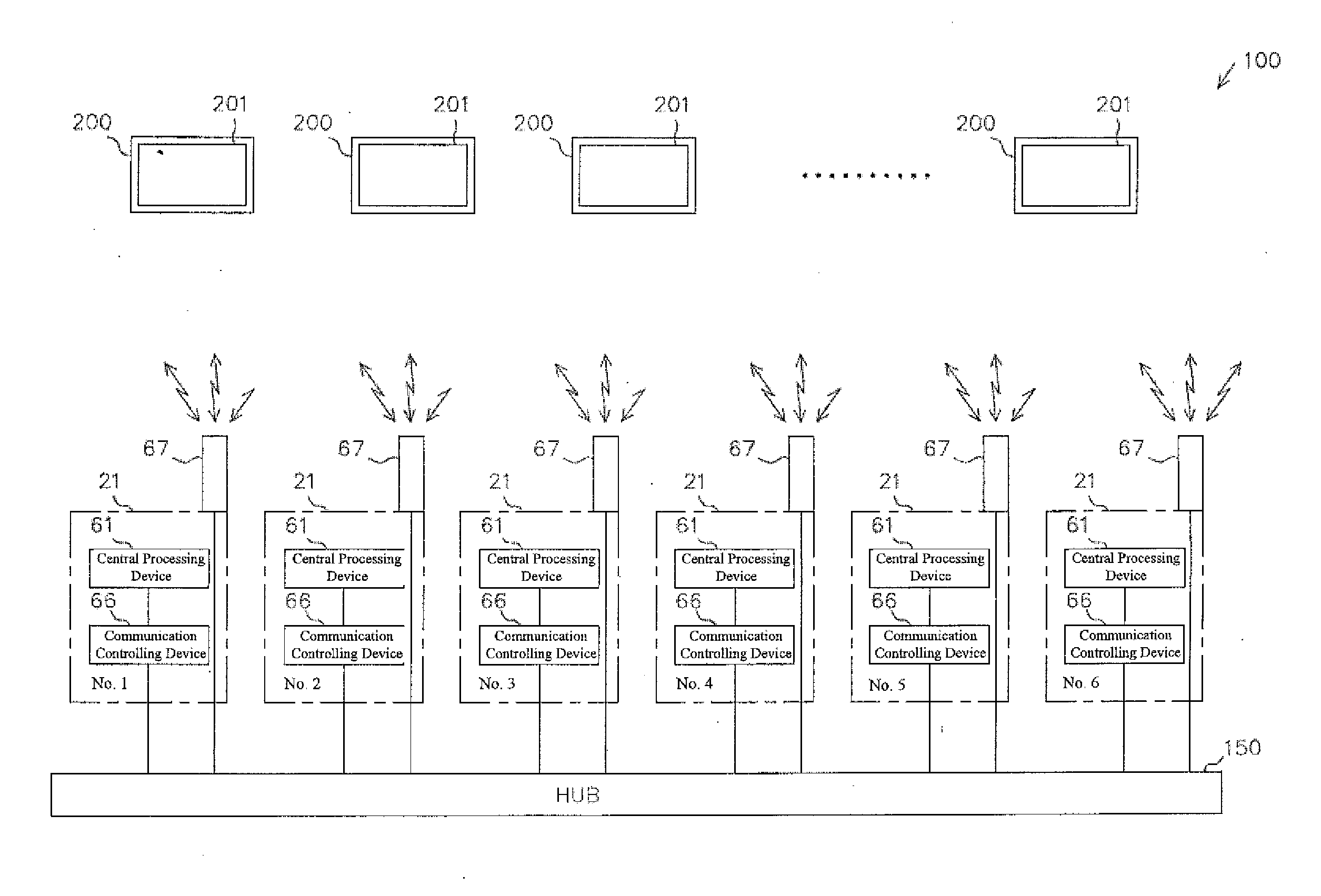
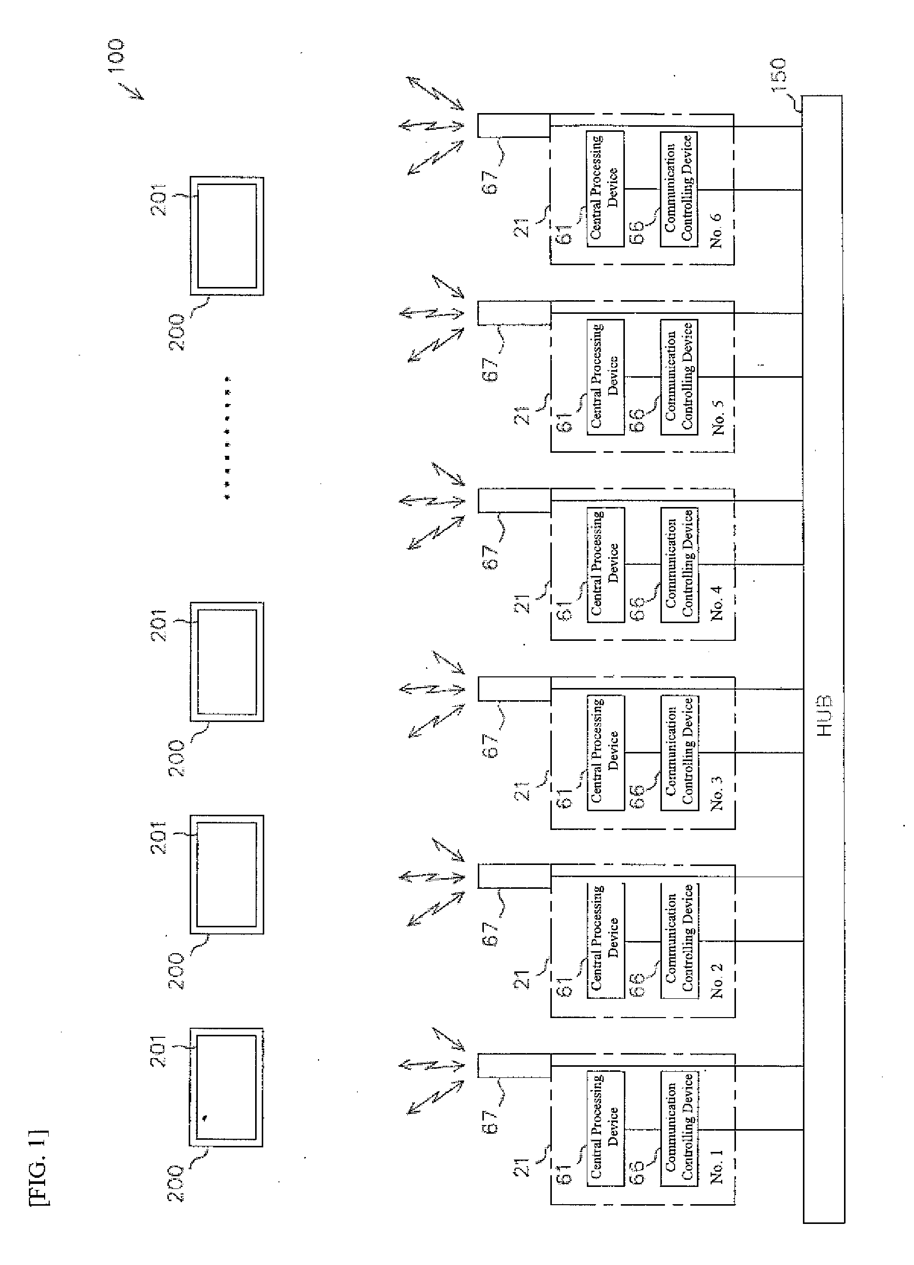
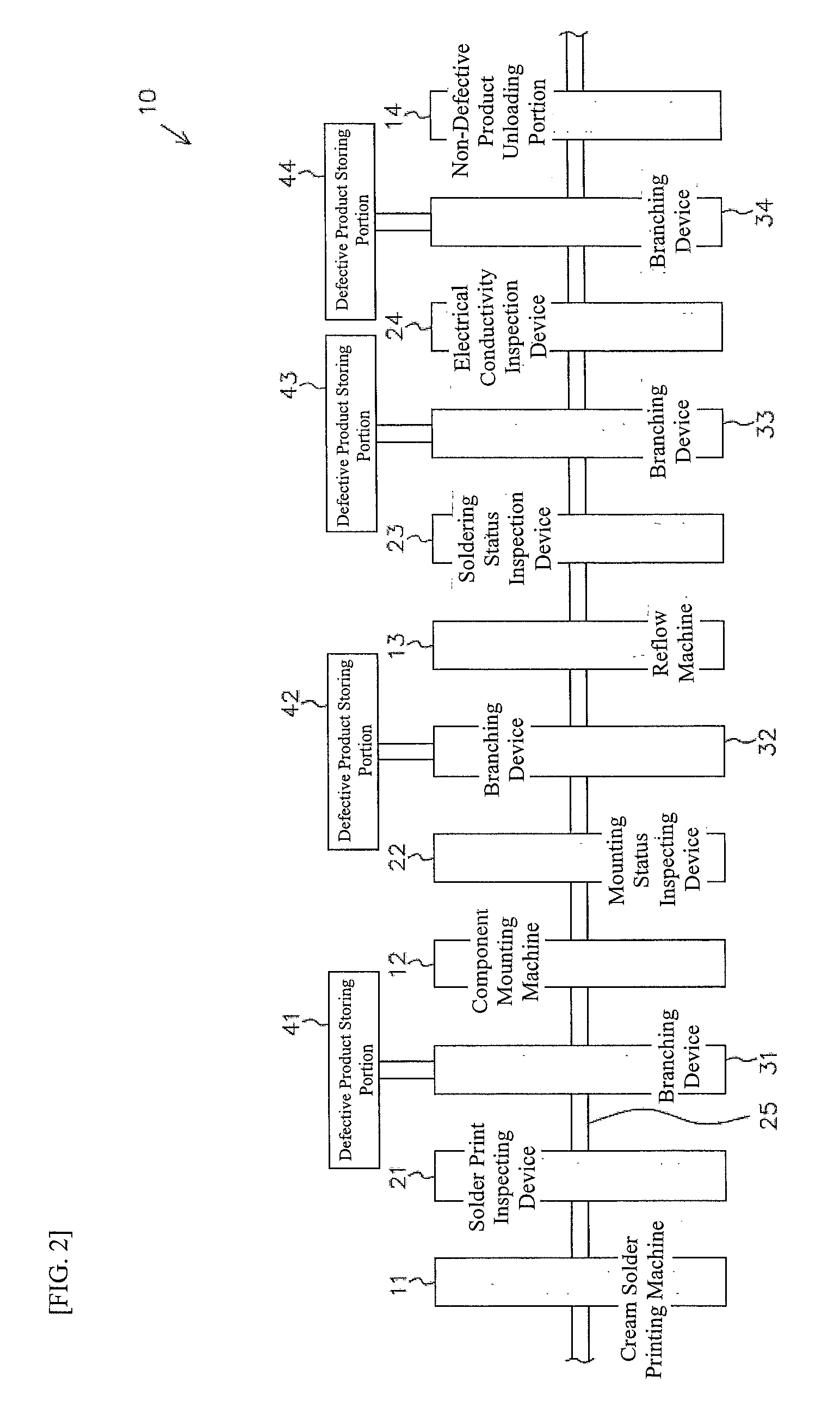
[0059]FIG. 1 is a structural diagram illustrating a schematic structure of an inspecting device monitoring system 100. FIG. 2 is a structural diagram illustrating a schematic structure for a printed substrate production line 10. FIG. 3 is a structural diagram illustrating a schematic structure of a solder print inspecting device 21 that is the subject of monitoring of the monitoring system 100.

[0060]Prior to explaining the monitoring system 100, the printed substrate production line 10 will be explained first.

[0061]As illustrated in FIG. 2, the production line 10 is provided with a cream solder printing machine 11, a component mounting machine 12, and a reflow machine 13, provided sequentially from the starting side (the left side in FIG. 2).

[0062]The cream solder printing machine 11 is a machine for printing a specific amount of cream solder 3 onto a land (pad) 2 that is provid...


PUM


Abstract

In a monitoring system, when there is an evaluation that a product is defective, in a solder print inspecting device that is subject to monitoring, that information is sent to a mobile terminal possessed by an operator. The operator who views the notification performs, through the mobile terminal, a checking task for evaluating whether or not the evaluation result regarding the printed substrate that has been evaluated as a defective product is correct. Depending on the evaluation result, an operating instruction is sent to the solder print inspecting device, which has temporarily stopped the printed substrate. If correction information instructing that the defective-product evaluation be corrected to a non-defective-product evaluation is sent from a mobile terminal to the solder print inspecting device, the solder print inspecting device corrects the defective-product evaluation to a non-defective-product evaluation, and releases the temporary stop of the printed substrate.

Description

CROSS-REFERENCE TO RELATED APPLICATIONS[0001]This application claims priority to Japanese Patent Application No. 2013-003782 filed on Jan. 11, 2013 in Japan.BACKGROUND OF INVENTION[0002]1. Field of the Invention[0003]The present invention relates to a monitoring system for monitoring the operating status of an inspecting device in a factory, or the like.[0004]2. Background Art[0005]In a production line for mounting electronic components on a printed substrate, or the like, first a cream solder is printed on the lands that are provided on the printed substrate. Following this, electronic components are temporarily secured based on the viscosity of the cream solder. Thereafter, the printed substrate is placed into a reflow oven to perform soldering through a specific reflow process.[0006]In such a production line, typically a solder inspecting device is provided in order to inspect the state of printing of the cream solder, and to reject a printed substrate that is evaluated as a defe...

Claims


Application Information

Patent Timeline
Patent Type & Authority Applications(United States)
IPC IPC(8): G05B19/418
CPCG05B19/41875G05B2219/32209G05B2219/37217H05K13/0817H05K13/083Y02P90/02
Inventor KAMIOKA, YOSUKEOKUDA, MANABUSUZUKI, SHINGO
Owner CKD
Why Eureka
Try Eureka