Mounting table and plasma processing apparatus

a technology of plasma processing and mounting table, which is applied in the direction of mechanical equipment, chucks, manufacturing tools, etc., can solve the problems of deterioration, inability to prevent abnormal discharge in the radial space, and worsen the quality of the processing target, so as to prevent abnormal discharge and eliminate the space

Active Publication Date: 2014-07-24
TOKYO ELECTRON LTD
View PDF19 Cites 23 Cited by
  • Summary
  • Abstract
  • Description
  • Claims
  • Application Information

AI Technical Summary

Benefits of technology

[0009]In this mounting table, an upper end part of the pin hole has a shape in which a diameter decreases gradually toward a lower end. An upper end part of the lifter pin has a shape in which a diameter decreases gradually toward a lower end to correspond to a shape of the upper end part of the pin hole. The upper end part of the lifter pin is in surface contact with the upper end part of the pin hole when the lifter pin is received in the pin hole. Therefore, when the lifter pin is received in the pin hole, it is possible to completely eliminate the space in the radial direction in the upper end part of the pin hole. Accordingly, it is possible to prevent abnormal discharge occurring between the lifter pin and the pin hole.

Problems solved by technology

Thus, in some cases, it may be impossible to prevent abnormal discharge in the radial space.
As a result, it may worsen the quality of the processing target and become a cause of yield deterioration.

Method used


Image

  • Mounting table and plasma processing apparatus
  • Mounting table and plasma processing apparatus
  • Mounting table and plasma processing apparatus

Examples


first embodiment

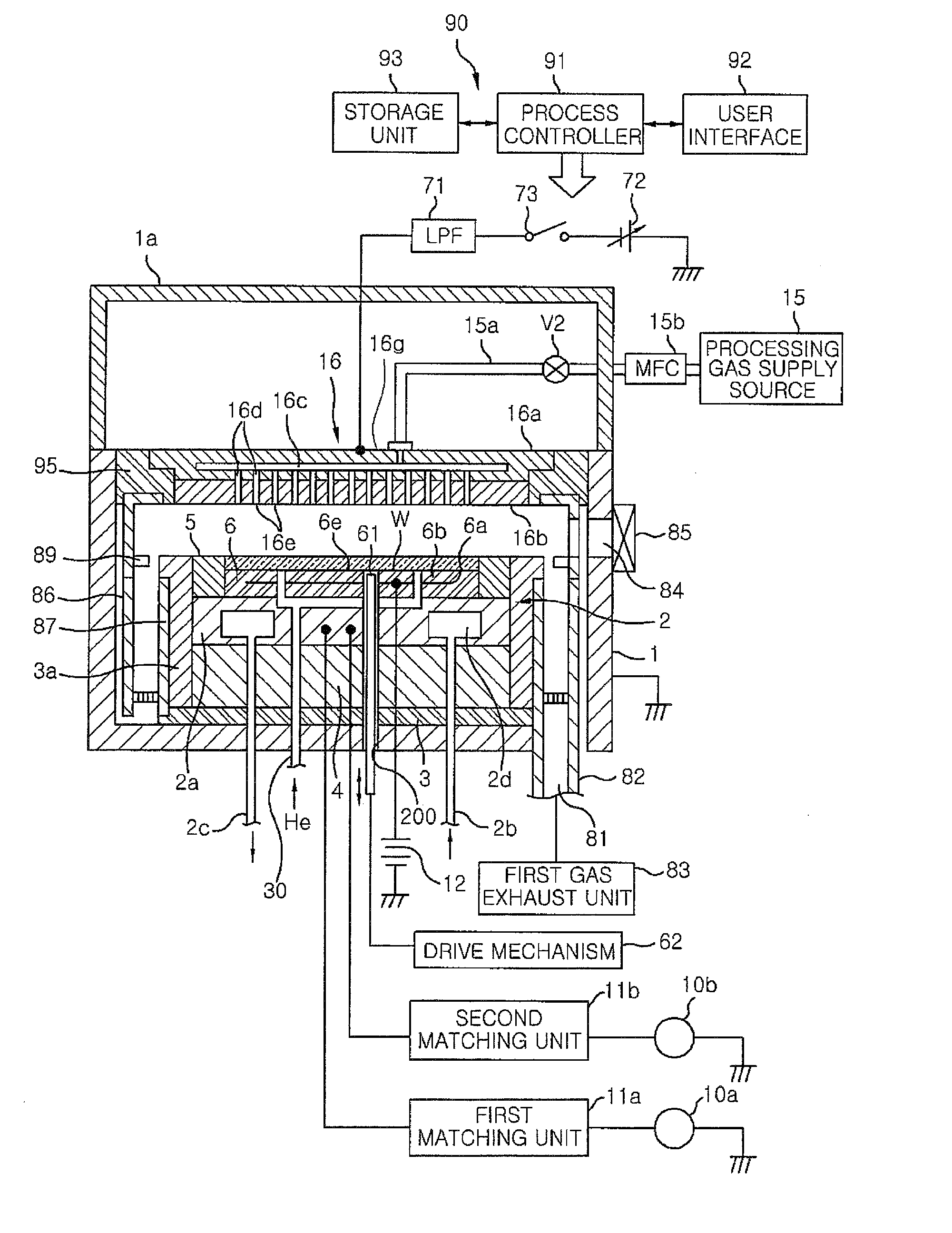
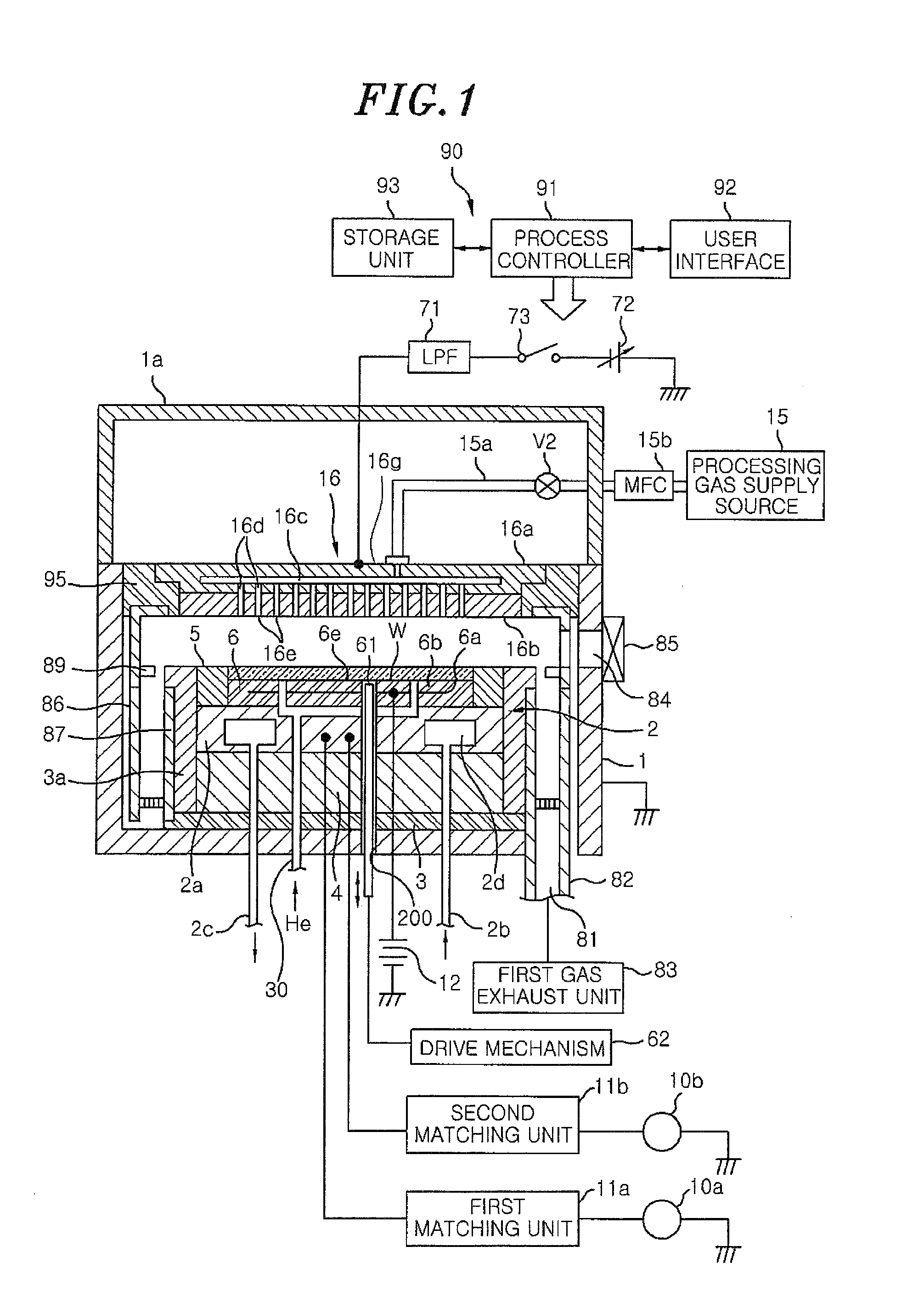
[0029]FIG. 1 is a schematic sectional view showing a configuration of a plasma processing apparatus according to an embodiment of the present invention. The plasma processing apparatus includes a processing chamber 1, which is airtightly sealed and is electrically grounded. The processing chamber 1 is formed in a cylindrical shape, and is made of, e.g., aluminum or the like. The processing chamber 1 defines a processing space in which a plasma is generated. In the processing chamber 1, there is provided a mounting table 2 for horizontally supporting a semiconductor wafer (hereinafter, simply referred to as “wafer”) W which is a processing target (work piece). The mounting table 2 is configured to include a base 2a and an electrostatic chuck 6. The base 2a is formed of conductive metal such as aluminum, and functions as a lower electrode. The electrostatic chuck 6 has a function of electrostatically attracting and holding the wafer W. The mounting table 2 is supported on a conductive...

second embodiment

[0069]However, in the mounting table 2 according to the first embodiment, as will be described below, further improvement may be made. FIG. 11 is a schematic diagram showing an outline of the drive mechanism 62 of the lifter pins 61 in the mounting table of FIG. 1. Further, FIG. 11 shows a case of the cross section in which two lifter pins 61 are shown. As shown in FIG. 11, the drive mechanism 62 includes a drive source 54 and a drive member 55 connected to the drive source 54. The drive member 55 has, e.g., a disk shape, and one point of the outer periphery is connected to the drive source 54. Accordingly, a vertical driving force is applied to the connection point with the drive source 54. Further, in the drive member 55, one point of the outer periphery of the drive member 55 opposite to the connection point with the drive source 54 is fixed. The lower ends of the lifter pins 61 are connected to the upper surface of the drive member 55. Although not shown in FIG. 11, three or mor...


PUM

PropertyMeasurementUnit
outer diameteraaaaaaaaaa
thicknessaaaaaaaaaa
pressureaaaaaaaaaa

Abstract

A mounting table includes an electrostatic chuck having a mounting surface and a backside opposite to the mounting surface, a first through hole being formed in the mounting table; a base joined to the backside of the electrostatic chuck and having a second through hole in communication with the first through hole; a lifter pin which is received in a pin hole formed by the first through hole and the second through hole, the lifter pin being movable up and down to protrude beyond and retract below the mounting surface. An upper end portion of the lifter pin has a shape in which a diameter decreases toward a lower end of the lifter pin to correspond to a shape of the upper end portion of the pin hole. The upper end portion of the lifter pin is in surface contact with the upper end portion of the pin hole.

Description

CROSS-REFERENCE TO RELATED APPLICATIONS[0001]This application claims priority to Japanese Patent Application No. 2013-009455 filed on Jan. 22, 2013 and U.S. Provisional Application Ser. No. 61 / 759,489 filed on Feb. 1, 2013, the entire contents of which are incorporated herein by reference.FIELD OF THE INVENTION[0002]The present invention relates to a mounting table and a plasma processing apparatus.BACKGROUND OF THE INVENTION[0003]As a conventional plasma processing apparatus, there has been known a plasma processing apparatus including an evacuable processing chamber; a mounting table for mounting thereon a processing target in the processing chamber, the mounting table serving as a lower electrode; and an upper electrode disposed to face the mounting table (see, e.g., Japanese Patent Application Publication Nos. 2011-238825 and 2000-195935). In the plasma processing apparatus described in Japanese Patent Application Publication Nos. 2011-238825 and 2000-195935, by applying high fr...

Claims


Application Information

Patent Timeline
Patent Type & Authority Applications(United States)
IPC IPC(8): H01J37/32H01L21/687H01L21/683
CPCH01J37/32009H01L21/68742H01L21/6833H01J37/32715H01J37/32733H01L21/6831Y10T279/23
Inventor YAMAGUCHI, SHINHAYASHI, DAISUKEKUDO, YASUHISA
Owner TOKYO ELECTRON LTD
Why Eureka
Try Eureka