Charged particle beam irradiation system and operating method of charged particle beam irradiation system

a technology of charged particle beam and irradiation system, which is applied in the field of charged particle beam irradiation system, can solve the problems of unnecessary charging of charged particle beam, and achieve the effect of improving accuracy

Active Publication Date: 2014-07-24
HITACHI LTD
View PDF2 Cites 9 Cited by
  • Summary
  • Abstract
  • Description
  • Claims
  • Application Information

AI Technical Summary

Benefits of technology

[0035]According to the present invention, by measuring dose distribution of a checking beam by using a multi-layer beam monitor provided in a beam damper device, it is possible to check the energy, the Bragg peak, and the irradiation depth of a charged particle beam, with which a patient is to be irradiated, just before an actual irradiation in real time.
[0036]Furthermore, in a case where any unexpected deviation occurs to an extraction beam, it is possible to isolate whether or not the deviation facto...

Problems solved by technology

On the other hand, in the charged particle irradiation system, among the charged particle beams extracted from the ch...

Method used


Image

  • Charged particle beam irradiation system and operating method of charged particle beam irradiation system
  • Charged particle beam irradiation system and operating method of charged particle beam irradiation system
  • Charged particle beam irradiation system and operating method of charged particle beam irradiation system

Examples


Embodiment Construction

[0044]Embodiments of the present invention are described herein.

[0045](Configuration)

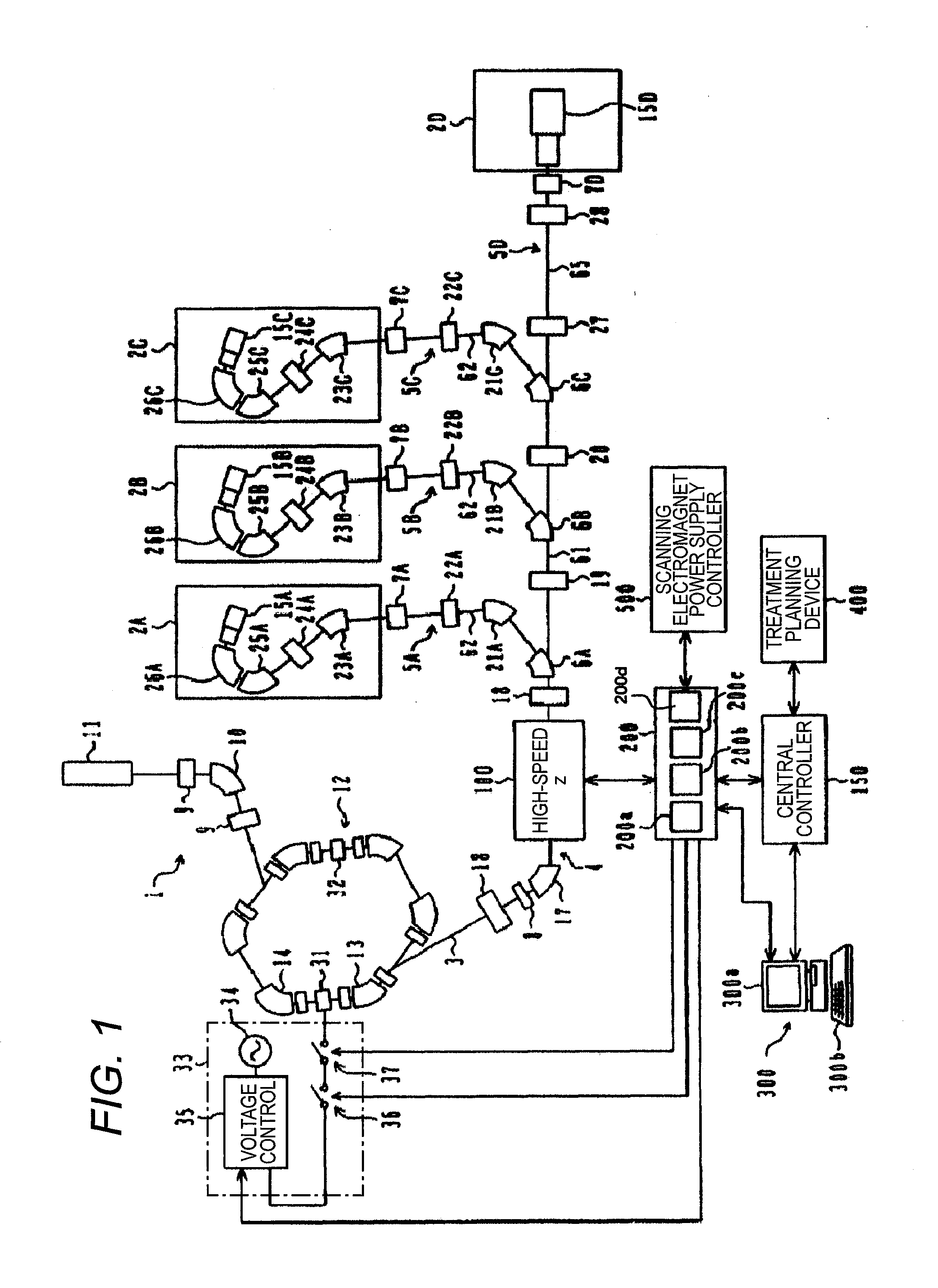
[0046]As illustrated in FIG. 1, a charged particle beam irradiation system according to this embodiment is provided with: a charged particle beam generator 1; a first beam transport line 4 connected on a downstream side of the charged particle beam generator 1; second beam transport lines 5A, 5B, 5C, and 5D respectively provided so as to diverge from the first beam transport line 4; switching electromagnets (pathway switching devices) 6A, 6B, and 6C; and irradiation devices 15A, 15B, 15C, and 15D, which are irradiation field forming devices. The first beam transport line 4 is a common beam transport line for leading an ion beam to each of the second beam transport lines 5A, 5B, 5C, and 5D. The second beam transport lines 5A, 5B, 5C, and 5D are beam transport lines provided for the irradiation devices 15A, 15B, 15C, and 15D, respectively. The irradiation devices 15A, 15B, 15C, and 15D are disposed in...


PUM


Abstract

A charged particle beam irradiation system in which the energy, Bragg peak, and irradiation depth of a charged particle beam, with which a patient is to be irradiated, can be checked in real time just before actual irradiation. Just before the actual irradiation, by providing a high-speed steering magnet with 100% current, a checking beam is intentionally hit into a beam damper. By using a dosimeter and a dose measuring device in front thereof, extraction beam intensity is measured. By using a multi-layer beam monitor, a dose distribution thereof is measured. Accordingly, just before the actual irradiation, the energy, Bragg peak, and irradiation depth of the charged particle beam, with which the patient is to be irradiated, can be checked accurately and in real time. When the beam has a desired dose distribution as a result of checking, continuously, extraction control is performed.

Description

TECHNICAL FIELD[0001]The present invention relates to a charged particle beam irradiation system, and more particularly, to charged particle beam irradiation system suitable for being applied to a particle beam therapy apparatus for treating an affected part by irradiating the affected part with charged particle beam such as a proton and a carbon ion.BACKGROUND ART[0002]There has been known a treatment method in which an affected part of a patient suffering from cancer and the like is irradiated with a charged particle beam (ion beam) such as a proton and carbon ion. A charged particle beam irradiation system (particle beam extraction system or charged particle beam extraction device) used in this treatment is provided with a charged particle beam generator, and the ion beam accelerated in the charged particle beam generator reaches an irradiation device installed in a rotating gantry by passing through a first beam transport line and a second beam transport line provided in the rot...

Claims


Application Information

Patent Timeline
IPC IPC(8): A61N5/10
CPCA61N5/1067A61N5/1075A61N5/1079A61N2005/1087H05H7/12H05H13/04H05H2007/008H05H2007/046
Inventor IWAMOTO, TOMOHISAMORIYAMA, KUNIONISHIUCHI, HIDEAKINIHONGI, HIDEAKI
Owner HITACHI LTD
Why Eureka
Try Eureka