Motor control device, and optical scanning device, image forming device and printed circuit board including the same
- Summary
- Abstract
- Description
- Claims
- Application Information
AI Technical Summary
Benefits of technology
Problems solved by technology
Method used
Image
Examples
embodiment 1
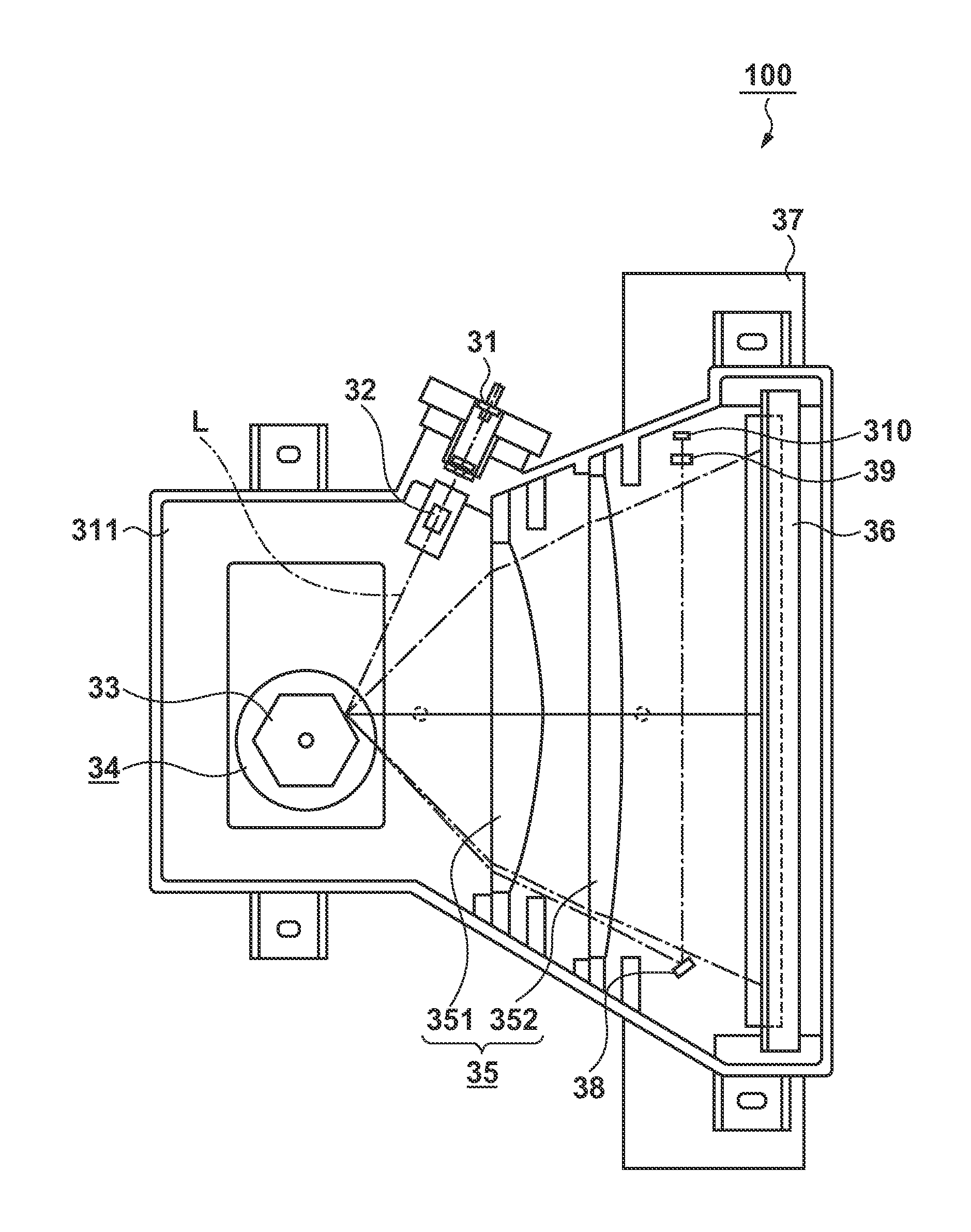
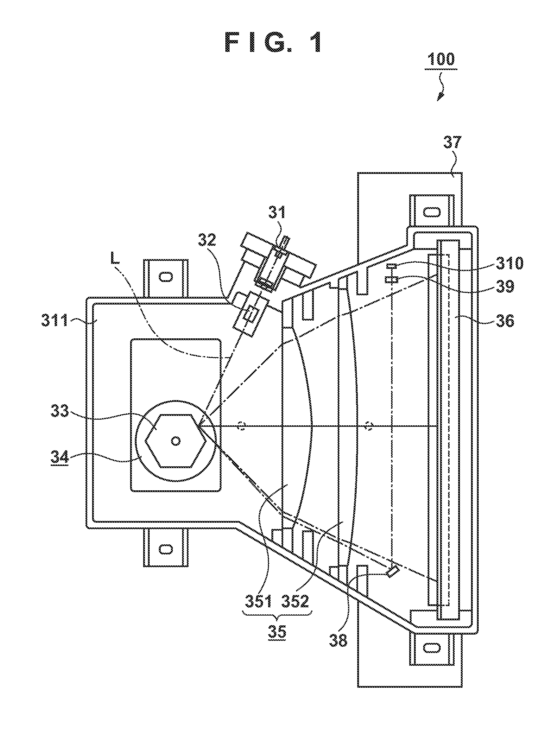
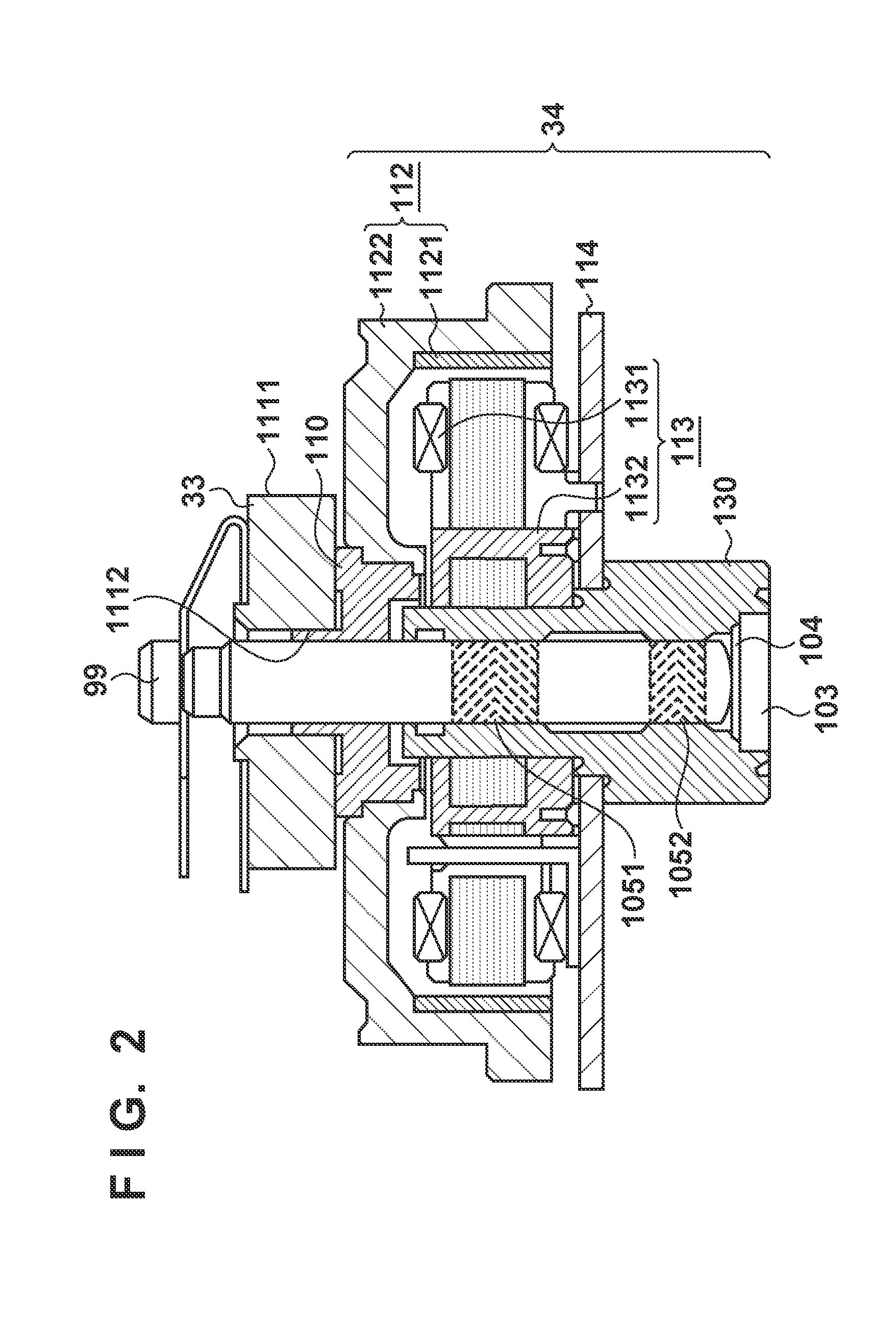
[0022]FIG. 1 shows a general optical scanning device 100 used in an electrophotographic image forming device. The optical scanning device 100 forms a latent image by irradiating an image carrier with light. A semiconductor laser unit 31 generates a laser beam L. After passing through a cylindrical lens 32, the laser beam L is deflected by a reflective surface of a rotating polygonal mirror 33. The rotating polygonal mirror 33 is driven by a deflection scanning device 34. The deflection scanning device 34 is constituted by a three-phase brushless motor. The deflection scanning device 34 may be called a scanner motor as it scans the image carrier using a deflected light beam. As such, the deflection scanning device 34 is one example of a motor that drives a rotating polygonal mirror for deflecting a light beam output from a light source. The laser beam L deflected by the rotating polygonal mirror 33 passes through Fθ lenses 35 and is deflected by a fold mirror 36. The Fθ lenses 35 are...
embodiment 2
[0045]The feature of Embodiment 2 is to detect a cycle of a Hall signal in the process of accelerating a motor and to detect the rotation direction when the cycle matches a cycle corresponding to a speed that is half of a rated rotation. It should be noted that the items that are the same as in Embodiment 1 are given the same reference signs to simplify the explanation.
[0046]FIG. 8 is a flowchart of motor control according to Embodiment 2. After S101 to S103 are executed, the processing moves to S201.
[0047]In S201, the CPU 1 determines whether or not the cycle of the Hall signal has reached a predetermined cycle (e.g. 960 μs). As the rotation speed of the motor increases, the cycle of the Hall signal gradually shortens. That is to say, the rotation speed (rotation frequency) of the motor is inversely proportional to the cycle of the Hall signal. When the cycle of the Hall signal has reached or fallen below the predetermined cycle, the processing moves to S202. As such, the CPU 1 fun...
embodiment 3
[0054]The following describes Embodiment 3 in detail with reference to an external view of FIG. 9. It should be noted that the matters that are the same as in Embodiments 1 and 2 are given the same reference signs to simplify the explanation.
[0055]As apparent from comparison between FIG. 5A and FIG. 9, a part of the printed circuit board 114 is removed in Embodiment 3 due to the arrangement of the deflection scanning device 34. In some cases, this removal is necessary to, for example, create a space for arranging an optical component such as a lens through which a light beam deflected by the rotating polygonal mirror 33 passes. When the printed circuit board 114 has this shape, it is necessary to arrange the drive control IC 101 obliquely with respect to the lengthwise direction of the printed circuit board 114 because of restrictions imposed by copper foil patterns on the drive control IC 101. Note that the oblique arrangement of the drive control IC 101 means that a main edge of t...
PUM
 Abstract
Description
Claims
Application Information
 - R&D
- Intellectual Property
- Life Sciences
- Materials
- Tech Scout
- Unparalleled Data Quality
- Higher Quality Content
- 60% Fewer Hallucinations
Browse by: Latest US Patents, China's latest patents, Technical Efficacy Thesaurus, Application Domain, Technology Topic, Popular Technical Reports.
© 2025 PatSnap. All rights reserved.Legal|Privacy policy|Modern Slavery Act Transparency Statement|Sitemap|About US| Contact US: help@patsnap.com


