Node device, communication system, and method for switching virtual switch

a communication system and virtual switch technology, applied in the field of node devices, communication systems, and methods for switching virtual switches, can solve the problems of inability to avoid failure, communication interrupt time considerably affecting normal work, and the application of the technique on the vm cannot be handled, so as to increase the time required for failure recovery processing and increase the communication interrupt time

Inactive Publication Date: 2014-07-24
HITACHI LTD
View PDF0 Cites 10 Cited by
  • Summary
  • Abstract
  • Description
  • Claims
  • Application Information

AI Technical Summary

Benefits of technology

[0012]Also, in the above technique, the redundant configuration is provided as a countermeasure against the failure to conduct the fail-over or the system switching. However, when the failure is not normally restored as with the above-mentioned failure, there is a need to also maintain the standby communication node device as a failure recovery processing, and the time required for the failure recovery processing has a potential to be increased.
[0013]In the failure monitoring or the countermeasure against the failure, a management server is installed outside to make it possible to grasp the overall system, and the countermeasure against the failure such as the fail-over to an appropriate physical server can be provided. However, when the failure is thus monitored or dealt with by the external management server, there is a possibility that failure risks such as congestion of the communication line or the failure in the management server increase. In association with this, the failure recovery processing is delayed to have a potential to increase the communication interrupt time.

Problems solved by technology

However, this technique does not deal with the failure in an application on the VM.
However, the failure cannot be avoided in the restart or fail-over of the VM, and thereafter the failure cause may be removed by another technique.
In this case, a time required for processing of the restart or fail-over is added to the communication interrupt time, resulting in a possibility that the communication interrupt time considerably affects a normal work.
As an example of the failure in the application, some trouble occurs due to update of the application or a configuration change.
The failure in the application may occur due to another cause.
However, when the failure is not normally restored as with the above-mentioned failure, there is a need to also maintain the standby communication node device as a failure recovery processing, and the time required for the failure recovery processing has a potential to be increased.
However, when the failure is thus monitored or dealt with by the external management server, there is a possibility that failure risks such as congestion of the communication line or the failure in the management server increase.
In association with this, the failure recovery processing is delayed to have a potential to increase the communication interrupt time.

Method used


Image

  • Node device, communication system, and method for switching virtual switch
  • Node device, communication system, and method for switching virtual switch
  • Node device, communication system, and method for switching virtual switch

Examples


first embodiment

[0054]In this embodiment, an appliance device conducts degenerate operation when a failure occurs in a virtual server.

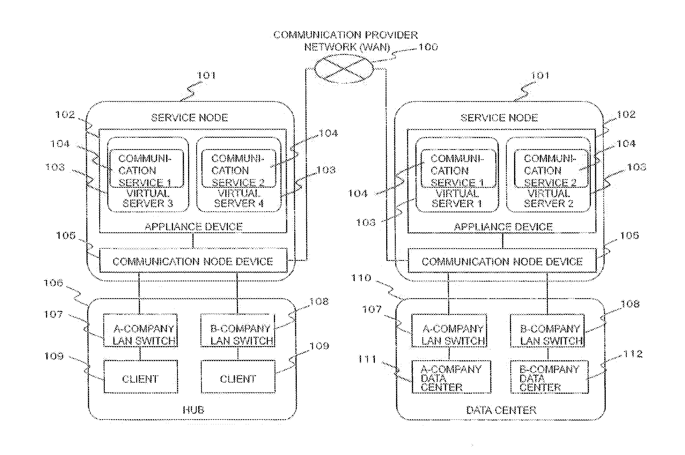
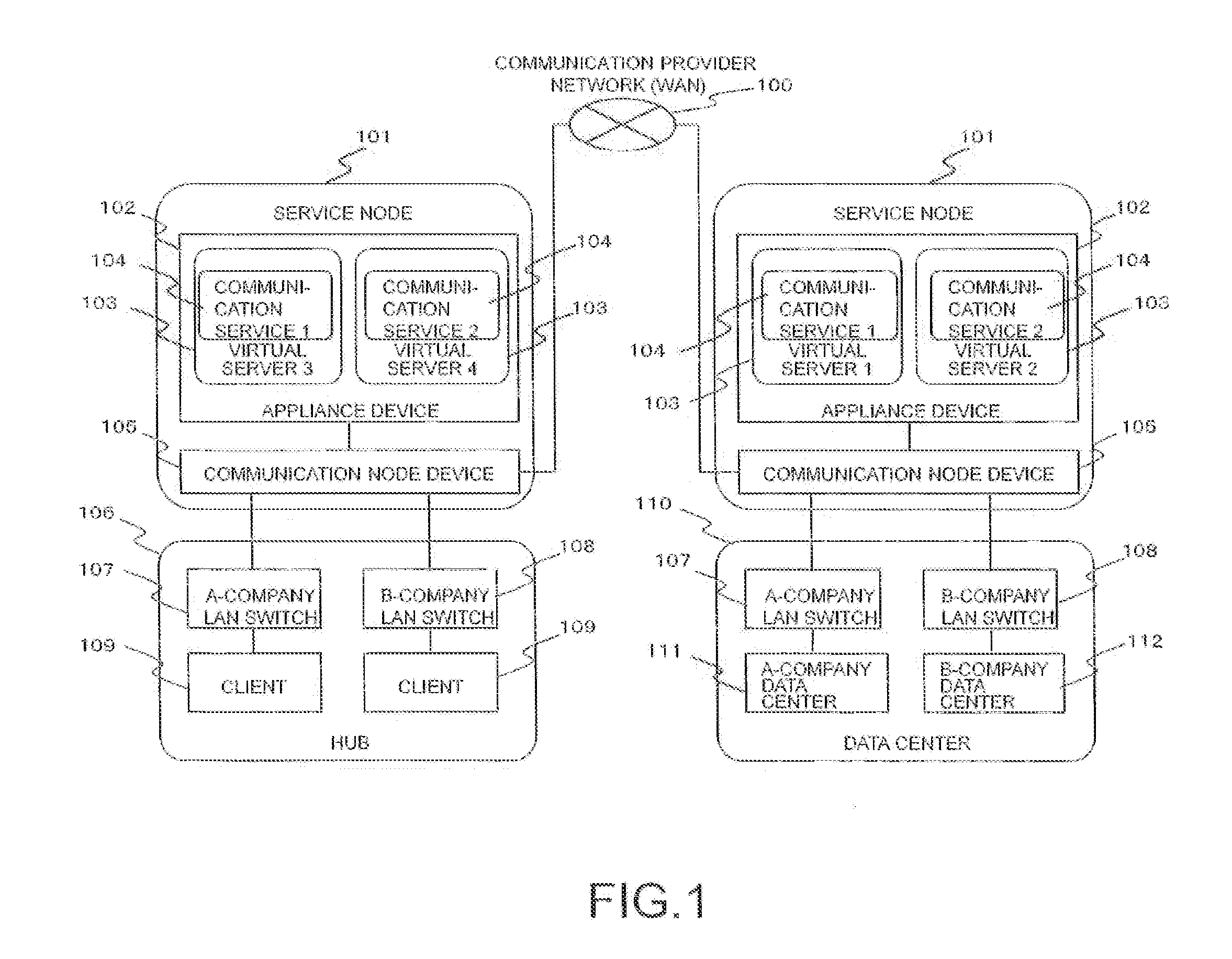
[0055]FIG. 1 is an exemplary configuration diagram of a virtual multitenant environment according to this embodiment. FIG. 1 illustrates an example in which clients (client devices) 109 in a hub 106 use a data center 110 via a WAN 100 with the use of communication services 104 provided by separate vendors (A company, B company). In the hub 106, the respective clients 109 are connected to an A-company LAW switch 107 or a B-company LAN switch 108 to conduct a communication.

[0056]Each of service nodes (node devices) 101 includes a communication node device 105 and an appliance device 102, and executes communication service processing (processing for providing a communication service, hereinafter called merely “communication services”) 104 to control communication data when the respective clients 109 and the data center 110 communicate with each other. For example, when ...

configuration example 1

[0106]A method for controlling a communication path of a virtual switch in a multitenant environment where a virtual machine that operates a plurality of software provides a communication service for cloud computing such as a WAN high-speed technology, the method comprising the steps of:

[0107]monitoring an operating status of the communication service of the virtual machine; and

[0108]conducting a communication control by changing the communication path and a communication method of the virtual machine according to an application of the communication service if a failure occurs in the application of the communication service of the virtual machine.

configuration example 2

[0109]The method for controlling the communication path of the virtual switch according to the configuration example 1, in which

[0110]if the communication service provides a function for changing the communication data in the virtual machine in which a failure is detected, the communication data is returned to a physical NIC of a physical machine that receives the communication data without transmitting the communication data to the virtual machine to continue the communication, and

[0111]if the communication service provides a function for filtering the communication from the external, the communication data is discarded without being transmitted to the virtual machine.


PUM


Abstract

When a failure occurs in a virtual machine (hereinafter called “VM”), degenerate operation not routed through the VM which is a failure target, and corresponding to a communication service on the VM is conducted to shorten a communication interrupt time. A communication path of a virtual switch in a multitenant environment where a virtual machine that operates a plurality of software provides a communication service for cloud computing such as a WAN high-speed technology is controlled. The control method, for example, comprises the steps of monitoring an operating status of the communication service of the virtual machine, and conducting a communication control by changing the communication path and a communication method of the virtual machine according to an application of the communication service if a failure occurs in the application of the communication service of one virtual machine.

Description

CLAIM OF PRIORITY[0001]The present application claims priority from Japanese patent application JP 2013-007799 filed on Jan. 18, 2013, the content of which is hereby incorporated by reference into this application.BACKGROUND OF THE INVENTION[0002]1. Field of the Invention[0003]The present invention relates to a node device, a communication system, and a method for switching a virtual switch, and more particularly to a node device, a communication system, and a method for switching a virtual switch, which controls a path route of the virtual switch to continue a communication when a failure occurs in a communication service on a virtual server.[0004]2. Description of the Background art[0005]With the spread of cloud computing, data centers provided by data center providers or communication carriers are increasingly used. In general, the data canters are frequently installed at remote locations, and accessed via a local area network (LAN) or a wide area network (WAN) in use.[0006]In th...

Claims


Application Information

Patent Timeline
Patent Type & Authority Applications(United States)
IPC IPC(8): H04L12/24H04L12/823H04L12/703H04L45/28H04L45/586H04L47/32
CPCH04L41/0654H04L45/28H04L47/32H04L49/70H04L63/02G06F11/1438G06F11/1484G06F11/301G06F11/3055G06F11/3409G06F11/3419G06F2201/815G06F11/0712G06F11/0757G06F11/0793
Inventor MIZUNO, KAZUHIKOTSUSHIMA, YUJIOKUNO, MICHITAKA
Owner HITACHI LTD
Why Eureka
Try Eureka