System and Method For Imaging Defects

a technology of imaging defects and defects, applied in the direction of material analysis by secondary emission, material analysis using wave/particle radiation, instruments, etc., can solve the problems of high cost and complexity of obtaining positron beams, structural and industrial materials failure costs the u.s. economy approximately $100 billion per year, and the application of doppler broadening spectroscopy techniques to basic materials science with little commercial or industrial application

Inactive Publication Date: 2014-07-24
IDAHO STATE UNIV & STATE BOARD OF EDUCATION
View PDF2 Cites 4 Cited by
  • Summary
  • Abstract
  • Description
  • Claims
  • Application Information

AI Technical Summary

Benefits of technology

[0002]The present invention is directed to a defect imaging device that overcomes these and other problems. The defect imaging device has an energy beam that is directed at a device under test. The energy beam creates positron deep within the material of the device under test. When the positrons combine with electrons in the material they produce a pair of annihilation photons. The annihilation photons are detected. The Doppler broadening of the annihilation photons is used to determine if a defect is present in the material. Three dimensional images of the device under test are created by directing the energy beam at different portions of the device under test. As a result, the invention is able to detect defects deep inside a device under test, such as an aircraft or a bridge.

Problems solved by technology

The failure of structural and industrial materials costs the U.S. economy approximately $100 billion per year.
However, the thickness of the samples under investigation by these methods is severely limited by the range of the impinging positrons inside the samples being tested, generally only tens of microns.
In addition, the high cost and complexity of obtaining positron beams has limited the application of Doppler broadening spectroscopy techniques to basic materials science with little commercial or industrial application.

Method used

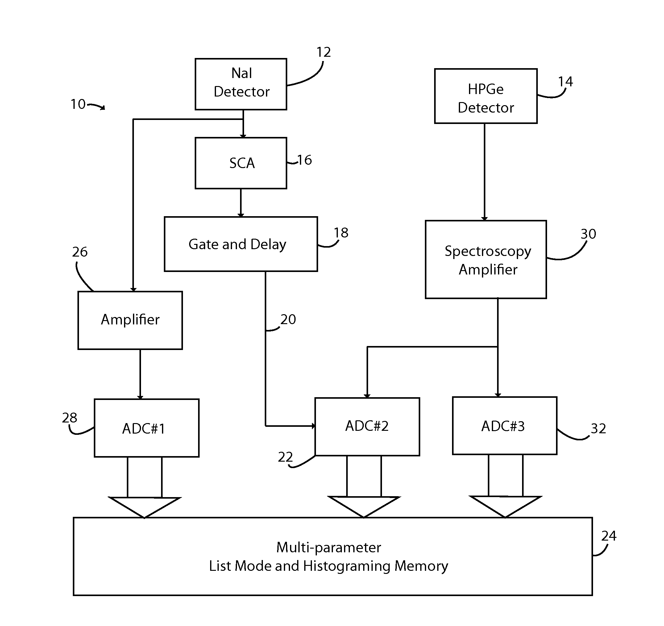
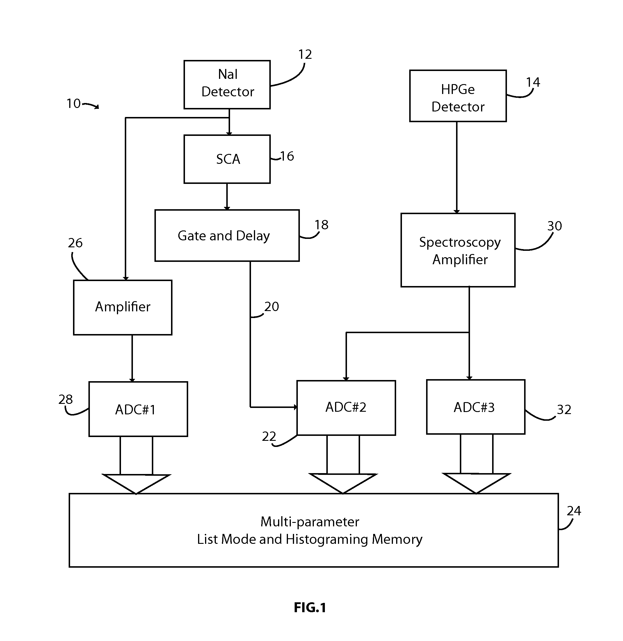
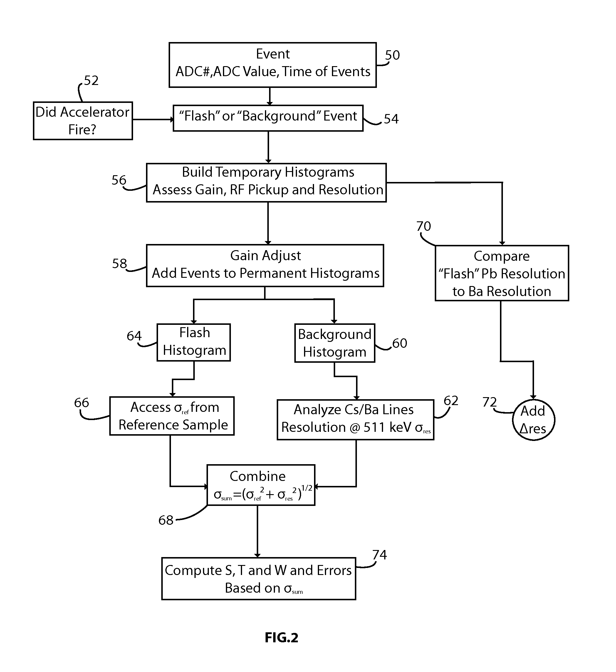

Image

  • System and Method For Imaging Defects
  • System and Method For Imaging Defects
  • System and Method For Imaging Defects

Examples


Embodiment Construction

[0010]The invention enables one to analyze any material for defects deep within the material, whether a result of manufacturing defects, stress, or otherwise, and to image the defects in two and three dimensions. The invention can be applied to static or dynamic objects and materials, does not create radiation above regulatory restrictions, and is portable and highly configurable so that it can be applied in a wide variety of manufacturing environments and to virtually any object or structure, wherever it may be located. The device described herein can be used to analyze defects in objects and structures, large and small, of any construction or composition; crystal, metal, alloy, polymer, welded, bonded, cast or formed.

[0011]The invention creates positrons deep within materials with photo-nuclear methods. Several methodologies are employed to do this. The first involves the use of a bremsstrahlung beam with a maximum energy above the neutron emission thresholds to produce residual n...


PUM

PropertyMeasurementUnit
radiation energyaaaaaaaaaa
Doppler energyaaaaaaaaaa
atomic numberaaaaaaaaaa

Abstract

The invention is directed to a defect imaging device that has an energy beam that is directed at a device under test. The energy beam creates positrons deep within the material of the device under test. When the positrons combine with electrons in the material they produce a pair of annihilation photons. The annihilation photons are detected. The Doppler broadening of the annihilation photons is used to determine if a defect is present in the material. Three dimensional images of the device under test are created by directing the energy beam at different portions of the device under test.

Description

BACKGROUND OF THE INVENTION[0001]The failure of structural and industrial materials costs the U.S. economy approximately $100 billion per year. Various non-destructive testing techniques have been employed over the years, one of them being Doppler broadening measurements using either slow positron beams or wide-energy spectrum positron beams originated from radioactive sources. However, the thickness of the samples under investigation by these methods is severely limited by the range of the impinging positrons inside the samples being tested, generally only tens of microns. In addition, the high cost and complexity of obtaining positron beams has limited the application of Doppler broadening spectroscopy techniques to basic materials science with little commercial or industrial application.BRIEF SUMMARY OF INVENTION[0002]The present invention is directed to a defect imaging device that overcomes these and other problems. The defect imaging device has an energy beam that is directed ...

Claims


Application Information

Patent Timeline
Patent Type & Authority Applications(United States)
IPC IPC(8): G01N23/223
CPCG01N23/22G01N2223/646G01N2223/108
Inventor HUNT, ALAN W.HERMON, J. FRANKWELLS, DOUGLAS P.
Owner IDAHO STATE UNIV & STATE BOARD OF EDUCATION
Why Eureka
Try Eureka