Iron pyrite thin films from molecular inks

a technology of iron pyrite and molecular ink, which is applied in the field of solar cells and iron pyrite thin film solar cell devices, can solve the problems of limited market share and societal impact of cdte and cigs, and the inability to meet the large increase in energy demand by existing carbon-based technologies without further destabilizing the climate, and achieve the effect of 0.3 tws or less of total solar conversion capacity for cdte and

a technology of iron pyrite and molecular ink, which is applied in the field of solar cells and iron pyrite thin film solar cell devices, can solve the problems of limited market share and societal impact of cdte and cigs, and the inability to meet the large increase in energy demand by existing carbon-based technologies without further destabilizing the climate, and achieve the effect of 0.3 tws or less of total solar conversion capacity for cdte and

US20140205756A1Active Publication Date: 2014-07-24RGT UNIV OF CALIFORNIA

Image

  • Iron pyrite thin films from molecular inks
  • Iron pyrite thin films from molecular inks
  • Iron pyrite thin films from molecular inks

Examples


Embodiment Construction

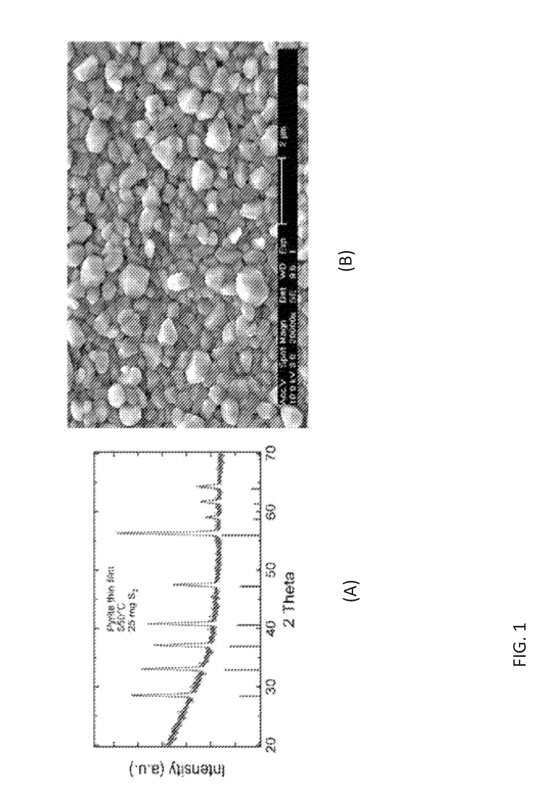
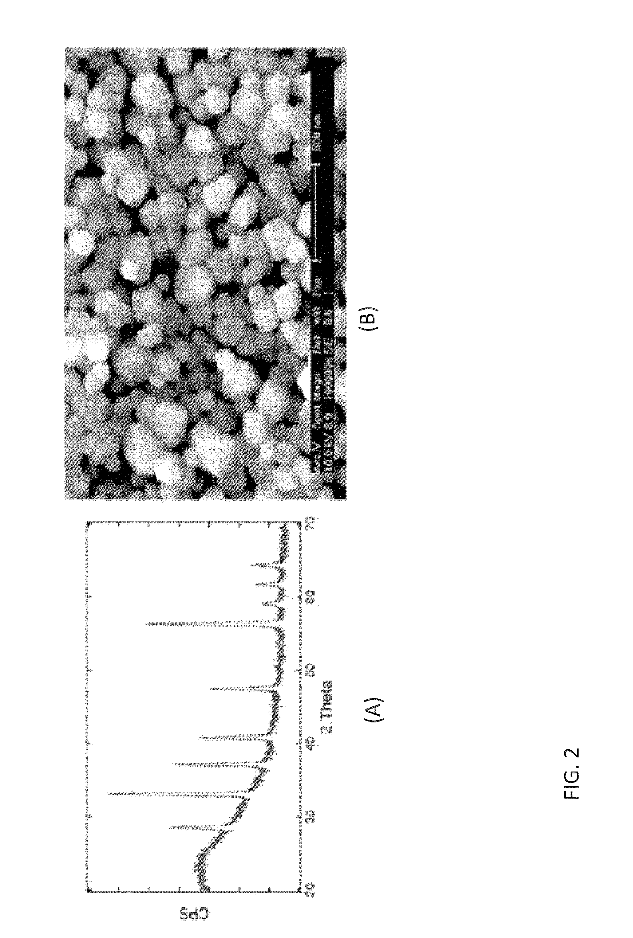
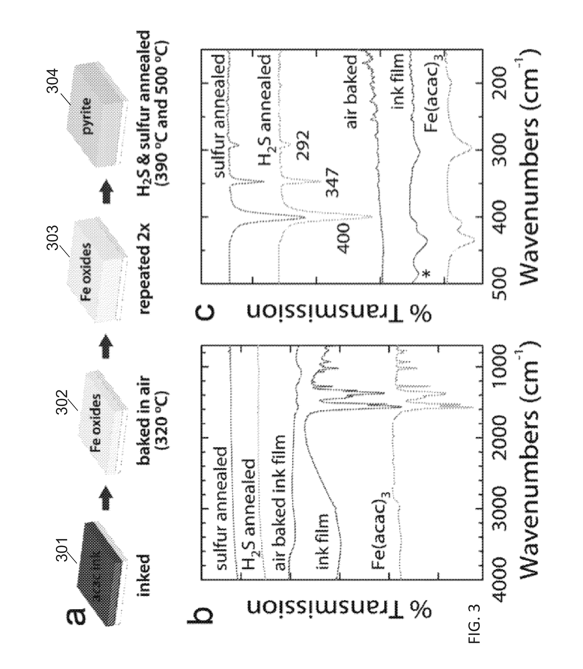
[0037]The embodiments provided herein are directed to systems and methods for fabricating pyrite thin films from molecular inks. A process is provided that comprises dissolving simple iron-bearing and sulfur-bearing molecules in an appropriate solvent and then depositing the solution onto an appropriate substrate using one of several methods (roll-to-roll coating, spraying, spin coating, etc.), resulting in a solid film consisting of the molecules. These molecular precursor films are then heated to 200-600° C. in the presence of sulfur-bearing gases (e.g., S2, H2S) to convert the molecular films into films of crystalline iron pyrite (FeS2). This approach offers the following advantages compared to gas-phase deposition and other solution-phase approaches:[0038]Simple and rapid deposition over large areas.[0039]Excellent control of film composition.[0040]Superior film uniformity.[0041]Simple doping and alloying.[0042]Low toxicity.[0043]Fairly low temperature.

[0044]Several solution che...


PUM


Abstract

Systems and methods are provided for fabricating pyrite thin films from molecular inks. A process is provided that comprises dissolving simple iron-bearing and sulfur-bearing molecules in an appropriate solvent and then depositing the solution onto an appropriate substrate using one of several methods (roll-to-roll coating, spraying, spin coating, etc.), resulting in a solid film consisting of the molecules. These molecular precursor films are then heated to 200-600° C. in the presence of sulfur-bearing gases (e.g., S2, H2S) to convert the molecular films into films of crystalline iron pyrite (FeS2).

Description

[0001]The present application claims the benefit of and priority to U.S. Provisional Application No. 61 / 754,461 titled “IRON PYRITE THIN FILMS FROM MOLECULAR INKS,” filed on Jan. 18, 2013, which is hereby incorporated by reference in its entirety.STATEMENT REGARDING FEDERALLY SPONSORED RESEARCH OR DEVELOPMENT[0002]This invention was made with Government support under Grant No. CHE-1035218, awarded by the National Science Foundation. The Government has certain rights in this invention.FIELD[0003]The embodiments relate generally to solar cells and iron pyrite thin film solar cell devices, and more particularly to methods for generating iron pyrite thin films from molecular inks.BACKGROUND[0004]The current annual global energy demand of ˜14 terawatt-years (TW-yrs) is expected to double by mid-century and triple by the end of the century. Such a large increase in energy demand cannot be met by the existing carbon-based technologies without further destabilizing the climate. The sun is t...

Claims


Application Information

Patent Timeline
24 Jul 2014
Publication
US20140205756A1
IPC
H01L31/18
CPC
H01L31/1864; H01L31/0336; H01L31/0368; Y02P70/50; B05D1/005; B05D1/02; B05D3/0254; B05D3/0453
Inventors
LAW, MATTHEW; WEBER, AMANDA S.