Transceiver with an integrated rx/tx configurable passive network

a passive network and transceiver technology, applied in the field of electronic devices, can solve the problems of t/r switch loss during both the transmitting function and receiving function of the transceiver, degrade the overall power efficiency and noise figure, and tg transistor loss

Inactive Publication Date: 2014-07-24
INTEL CORP
View PDF15 Cites 20 Cited by
  • Summary
  • Abstract
  • Description
  • Claims
  • Application Information

AI Technical Summary

Problems solved by technology

A typical T/R switch may introduce loss during both the transmitting function and receiving function of the transceiver by adding resistance and parasitic capacitive loads to the signal paths.
These losses may degrade overall power efficiency and noise figure...

Method used


Image

  • Transceiver with an integrated rx/tx configurable passive network
  • Transceiver with an integrated rx/tx configurable passive network
  • Transceiver with an integrated rx/tx configurable passive network

Examples


Embodiment Construction

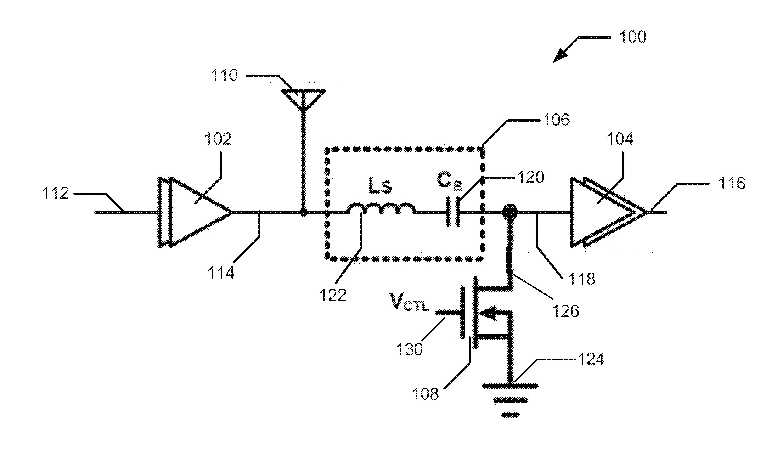
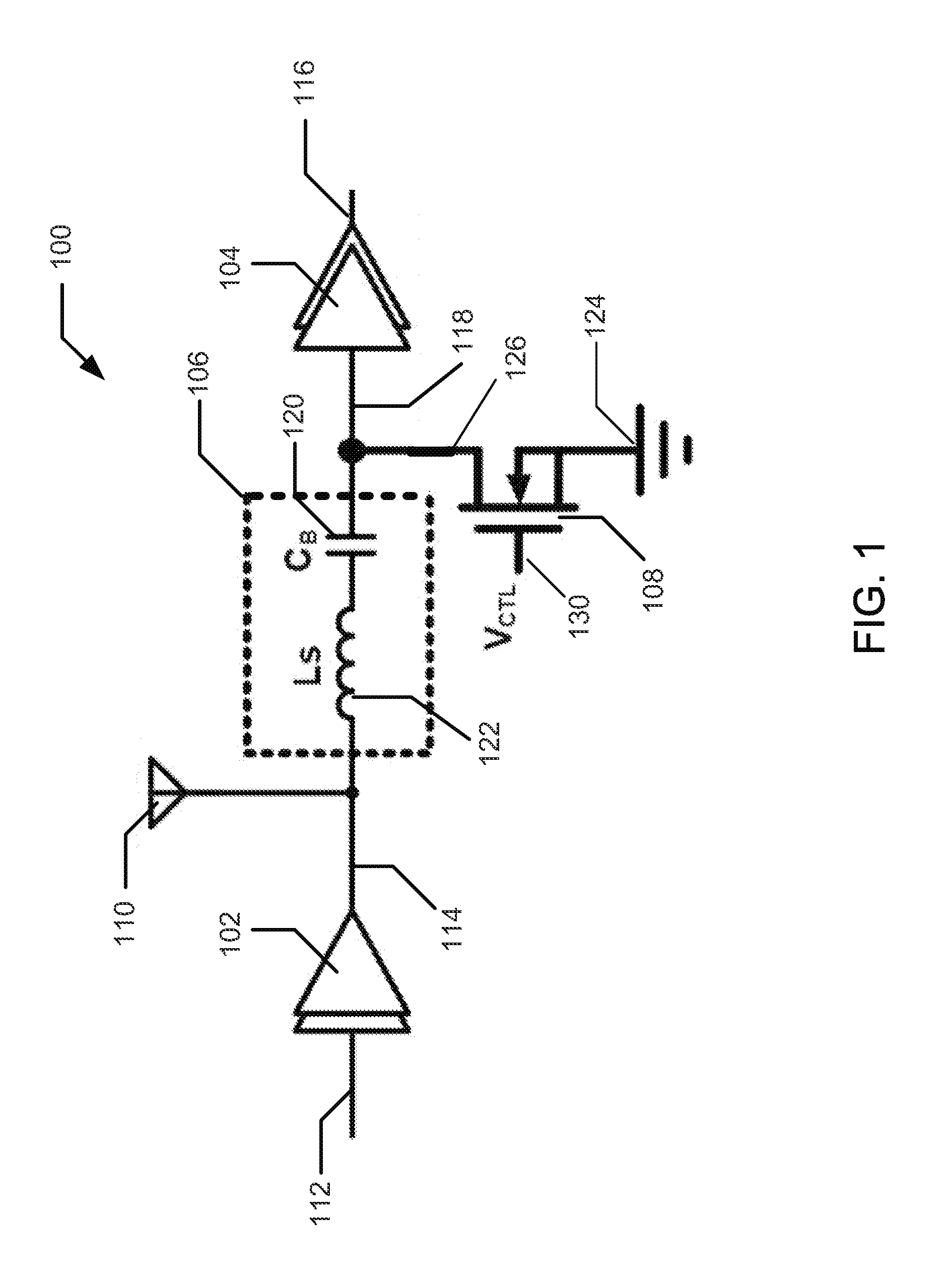
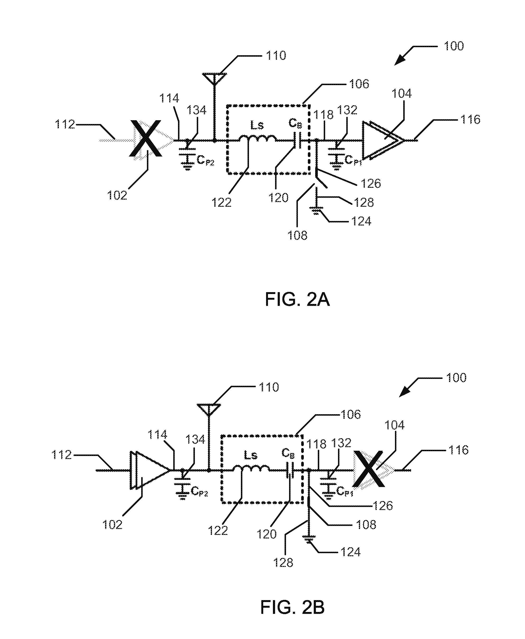
[0008]Embodiments of the present disclosure may relate to a radio frequency (RF) front-end. In embodiments, the radio frequency (RF) front-end may include a transceiver having a transmitter amplifier and a receiver amplifier. A transmission line may be coupled between the transmitter amplifier, receiver amplifier, and an antenna. A passive network may also be coupled between the transmitter amplifier and receiver amplifier and be configurable to cancel a reactance of a parasitic capacitance of the transmitter amplifier or to cancel a reactance of a parasitic capacitance of the receiver amplifier. The passive network may be switchably coupled to a voltage reference, such as ground, to enable operation of the transceiver without having a switch coupled in series between the antenna, the transmitter amplifier, and / or the receiver amplifier. The integrated T / R switch may be positioned in the transceiver so as to multiplex the antenna between the transmitter amplifier and the receiver am...


PUM


Abstract

Disclosed is an apparatus including a transmitter amplifier having an output terminal communicatively coupled to a transmission line to output a first set of radio frequency (RF) signals to an antenna. The apparatus may include a receiver amplifier having an input terminal communicatively coupled to the transmission line to receive a second set of RF signals from the antenna. The apparatus may include a passive network coupled between the transmitter amplifier and the receiver amplifier, the passive network being configurable to cancel either a first reactance of a parasitic capacitance of the transmitter amplifier or second reactance of a parasitic capacitance of the receiver amplifier. The apparatus may also include a switch coupled between the input terminal and a voltage reference to selectively configure the passive network to cancel either the first reactance or the second reactance. Other embodiments may be described and claimed.

Description

TECHNICAL FIELD[0001]The present disclosure relates generally to the technical field of electronics. More specifically, the present disclosure relates to a transceiver having an integrated configurable passive network.BACKGROUND INFORMATION[0002]A radio frequency (RF) front end may include a transceiver coupled to an antenna. A radio transceiver may include a transmitter, a receiver, and a transmit / receive (T / R) switch coupled electrically in series between the antenna, transmitter, and / or receiver. The T / R switch may multiplex an antenna to the transmitter or multiplex the antenna to the receiver. A typical T / R switch may introduce loss during both the transmitting function and receiving function of the transceiver by adding resistance and parasitic capacitive loads to the signal paths. These losses may degrade overall power efficiency and noise figure. To overcome these losses, conventional approaches may employ large T / R switches with low ON resistance (e.g., less than 5 ohms). A...

Claims


Application Information

Patent Timeline
IPC IPC(8): H04B1/44H04B15/02
CPCH03H7/40H04B1/44H04B1/0458H04B1/18H04B15/02
Inventor GEDDADA, HEMASUNDAR MOHANXU, HONGTAOFU, CHANG-TSUNGTAYLOR, STEWART S.
Owner INTEL CORP
Why Eureka
Try Eureka