
Method and apparatus for placing a catheter within a vasculature

a vasculature and catheter technology, applied in the field of catheters, can solve the problems of procedural failure, major obstacle within a chronic total occlusion, and still suffer from several drawbacks in the percutaneous treatment process

Active Publication Date: 2014-07-24
ROXWOOD MEDICAL
View PDF1 Cites 29 Cited by
  • Summary
  • Abstract
  • Description
  • Claims
  • Application Information

AI Technical Summary

Benefits of technology

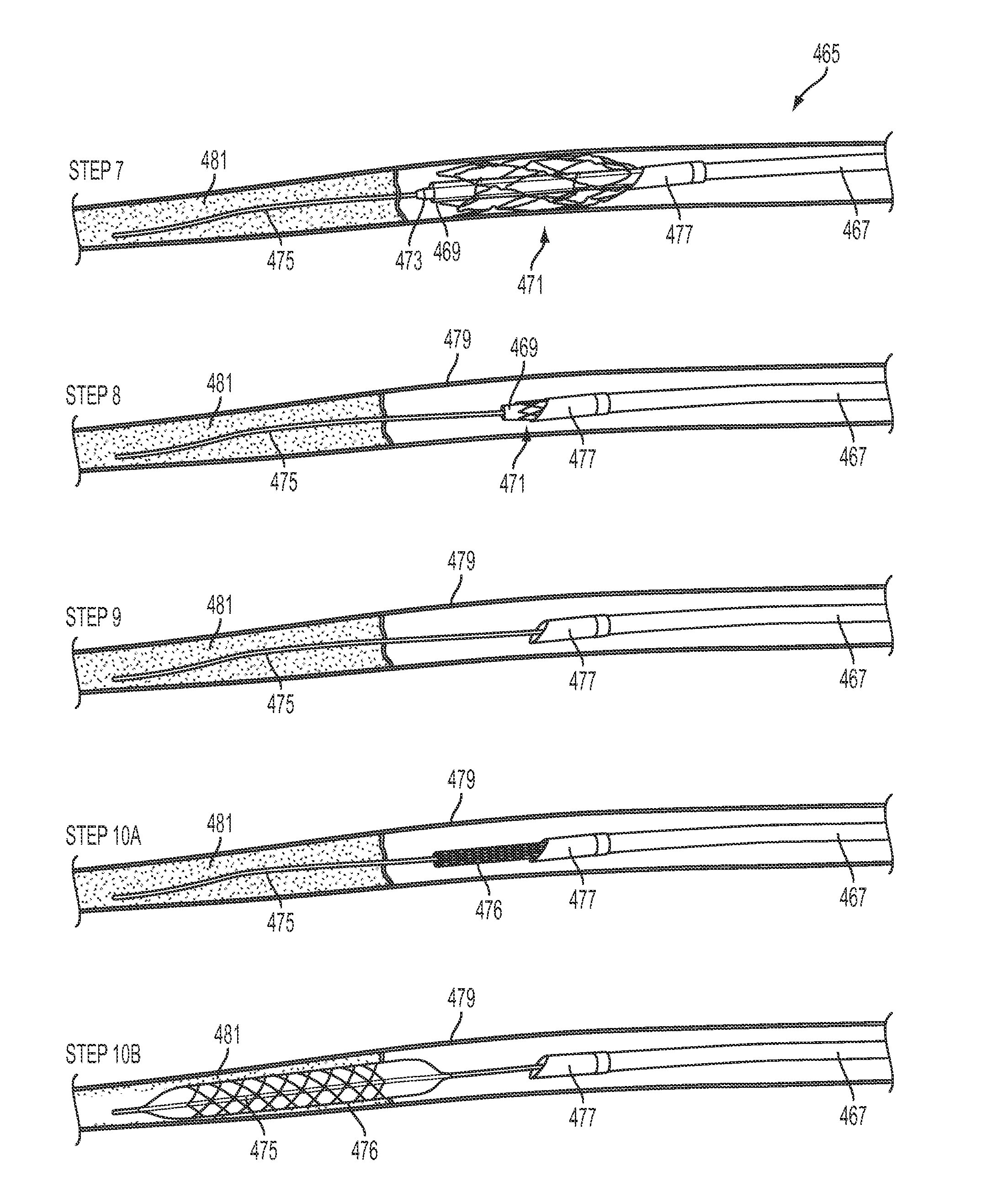
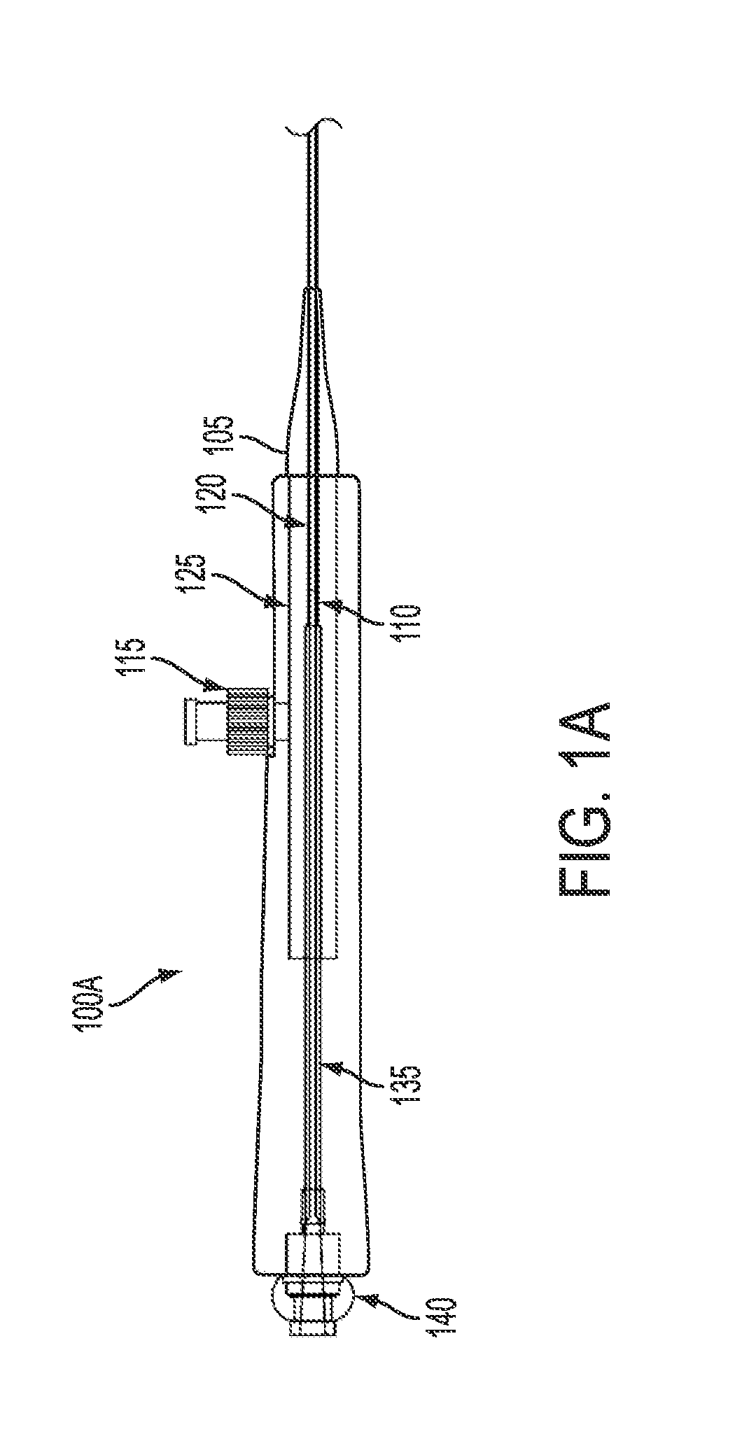
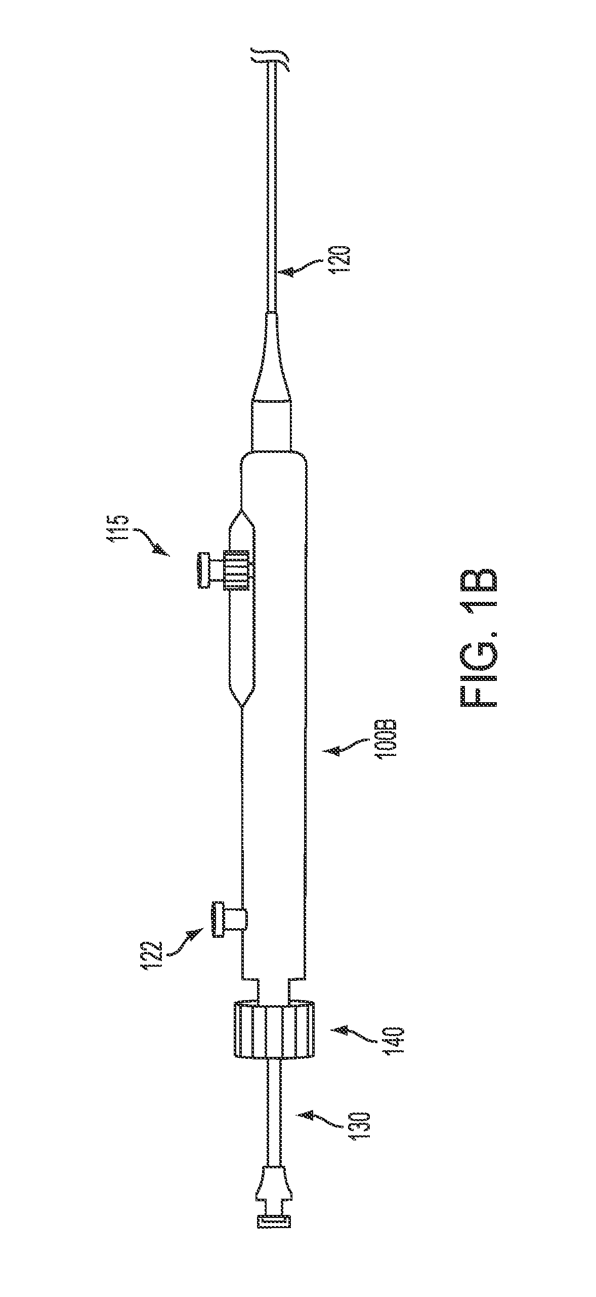
The invention is a catheter apparatus for use in treating defects in the vasculature of a patient. It includes a device for crossing a target area and providing support for a medical device. This device includes a hollow shaft with a self-expandable scaffold at the end. The scaffold can be expanded by withdrawing a sheath covering it. The method involves positioning the scaffold over a guidewire, removing the sheath, and advancing a medical device through the scaffold and sheath to the target area. The technical effect of this invention is to provide a new apparatus and method for treating vascular defects that provides better support and reliable placement of a medical device at the target area.

Problems solved by technology

A chronic total occlusion in a coronary artery, peripheral artery, vein, dialysis fistula, or other types of vasculature represents a challenge for percutaneous treatment.
Although the success rates for these types of procedures have improved, the procedures for percutaneous treatments still suffer from several drawbacks.
A major obstacle within a chronic total occlusion may often be encountered while attempting to advance a catheter across the chronic total occlusion in a vasculature.
This off-axis displacement of the catheter often may result in a procedural failure.
Successful passage of the catheter may also be obstructed by randomly located calcified regions of atherosclerotic plaque within the mass of the lesion.
However, these soft spots within the lesion are difficult to identify angiographically and are dispersed randomly within the matrix of the lesion.
The success of current technology is limited by this type of geometry.
As a result, only a minor portion of the surface area of the obstruction may be encountered with sufficient force to allow passage of the catheter.
On many occasions, the angle of encounter and / or the force applied to the fibrous cap may not be sufficient for crossing the fibrous cap with the catheter.
If the tip of the catheter is curved prior to placement through the support catheter, direct longitudinal force may be compromised as the wire is advanced off axis.
If a rapid exchange catheter system is used as catheter support, the catheter may buckle within the guide-catheter resulting in suboptimal longitudinal catheter force.
The angioplasty balloon, however, is occlusive to nearby vessels and exerts a significant outward force on the native vessel.
Despite overwhelming evidence of improved outcomes, attempted interventions remain low due to the lack of effective and convenient interventional tools.
CTOs are characterized by fibrous caps with small micro-channels often in tortuous anatomy, leading to challenges for clinicians to gain guidewire access to treat the underlying disease.
However, the usual risks of the catheter being diverted off-course remain.
Additionally, even if a guide wire is used, passage of the catheter through this anatomy can be traumatic for vessel walls.

Method used


Image

  • Method and apparatus for placing a catheter within a vasculature
  • Method and apparatus for placing a catheter within a vasculature
  • Method and apparatus for placing a catheter within a vasculature

Examples


Embodiment Construction

[0050]Embodiments of the present invention solve many of the problems and / or overcome many of the drawbacks and disadvantages of the prior art by providing an apparatus and method for treating vasculatures.

[0051]Embodiments of the present invention may include an apparatus and methods for advancing one or more catheters, preferably, microcatheters through chronic total occlusions in the vasculature. The support and centering functionality has application beyond CTOs, even though the preferred embodiments described herein are directed to support and centering to facilitate a guidewire to cross through a CTO.

[0052]In particular, embodiments of the invention may accomplish this with an apparatus for efficiently and effectively passing a microcatheter through the center of a chronic total occlusion in a vasculature. In particular, embodiments of the invention provide for apparatus and methods for centering a microcatheter within a vasculature, and for simplifying the insertion of multip...


PUM


Abstract

A catheter for insertion into vasculature of a patient to a target area in the vasculature includes a hollow inner shaft, a non-occluding self-expandable scaffold coupled to the distal end of the inner shaft and disposed at the distal end of the inner shaft, and a hollow outer shaft. The outer shaft is slidable over the inner shaft and scaffold such that the scaffold is in a non-expanded state when the outer shaft is around the scaffold. The outer shaft has a state where the distal end of the outer shaft remains near the target area without the inner shaft and the scaffold being within the outer shaft. The inner shaft and the scaffold are removable through the proximal end of the outer shaft while the distal end of the outer shaft remains near the target area.

Description

CROSS-REFERENCE TO RELATED APPLICATIONS[0001]This application is a continuation-in-part of U.S. patent application Ser. No. 14 / 060,381 filed Oct. 22, 2013, which claims priority to U.S. application Ser. No. 13 / 842,744, filed Mar. 15, 2013, U.S. Provisional Application No. 61 / 793,268, filed Mar. 15, 2013, and U.S. Provisional Application No. 61 / 716,856, filed Oct. 22, 2012, the contents of each of which are incorporated by reference in their entireties.[0002]This application is also a continuation-in-part of U.S. application Ser. No. 13 / 842,744, filed Mar. 15, 2013, which is a continuation-in-part application of U.S. application Ser. No. 13 / 166,623, filed Jun. 22, 2011, which is a divisional application of U.S. application Ser. No. 12 / 147,130, filed Jun. 26, 2008 (now U.S. Pat. No. 7,988,646 (issued Aug. 2, 2011)), which claims priority to U.S. Provisional Application No. 60 / 929,395, filed Jun. 26, 2007, U.S. Provisional Application No. 60 / 960,900, filed Oct. 19, 2007, and U.S. Provi...

Claims


Application Information

Patent Timeline
Patent Type & Authority Applications(United States)
IPC IPC(8): A61B17/3207
CPCA61B17/320725A61B17/3207A61B2017/22042A61B2017/22044A61B2017/22069A61B2017/22094A61M25/04A61M25/104A61M2025/0042A61M2025/09175A61M2025/09183
Inventor FARHANGNIA, MEHRDADMILLER, JOHNTABER, MARKYANG, MARK C.
Owner ROXWOOD MEDICAL
Learn More