Supercharge Your Innovation With Domain-Expert AI Agents!

Fuel supply system, scramjet engine and method for operating the same

a fuel supply system and scramjet technology, applied in the field of scramjet engines, can solve the problems of difficult control of the temperature of the catalyst arranged near the combustion chamber to be the desired temperature, the inability to increase the fuel on board, and the inability to achieve supersonic combustion (supersonic flight) for long periods of time, so as to achieve stably supply a reformed fuel, enhance heat energy efficiency, and use stably

Active Publication Date: 2014-07-31
MITSUBISHI HEAVY IND LTD
View PDF4 Cites 10 Cited by
  • Summary
  • Abstract
  • Description
  • Claims
  • Application Information

AI Technical Summary

Benefits of technology

The present invention relates to a fuel supply system, scramjet engine and method for operating them. The system is capable of decomposing fuel by heat to generate a reformed fuel which is then stable supplied to the engine for combustion. By using the reformed fuel, the engine can enhance heat energy efficiency. The invention also provides a stable method for using a reforming catalyst for pyrolysis in the engine. Overall, the invention enables a stable supply of fuel and improved performance of scramjet engines.

Problems solved by technology

Also, since the hydrocarbon with small carbon number is a gas state at normal temperature, when the hydrocarbon with small carbon number is mounted on a fuel tank, Fuel on Board cannot be increased and supersonic combustion (supersonic flight) cannot be realized for long periods of time.
However, since a temperature of a combustion chamber of the scramjet engine is very high and is equal to or more than thousands degrees C., it is very difficult to control a temperature of the catalyst arranged near the combustion chamber to be a desired temperature by using a heat generated by the combustion chamber.
When the heat supplied to a catalytic layer is excessive, there is a possibility that the temperature of the catalyst becomes too high, the catalyst is inactivated, heat decomposition becomes difficult, and generation of the reformed fuel becomes difficult.
Furthermore, when a temperature of a catalytic reaction region is unstable, there is a possibility that fuels of liquid state and gas state are mixed, the catalyst is stripped from a flow channel by vaporization / bumping of fuels to block the flow channel, and supply of the reformed fuel becomes difficult.

Method used


Image

  • Fuel supply system, scramjet engine and method for operating the same
  • Fuel supply system, scramjet engine and method for operating the same
  • Fuel supply system, scramjet engine and method for operating the same

Examples


Embodiment Construction

[0035]Hereinafter, referring to the attached drawings, a fuel supply system, a scramjet engine and a method for operating the same according to the present embodiment will be explained.

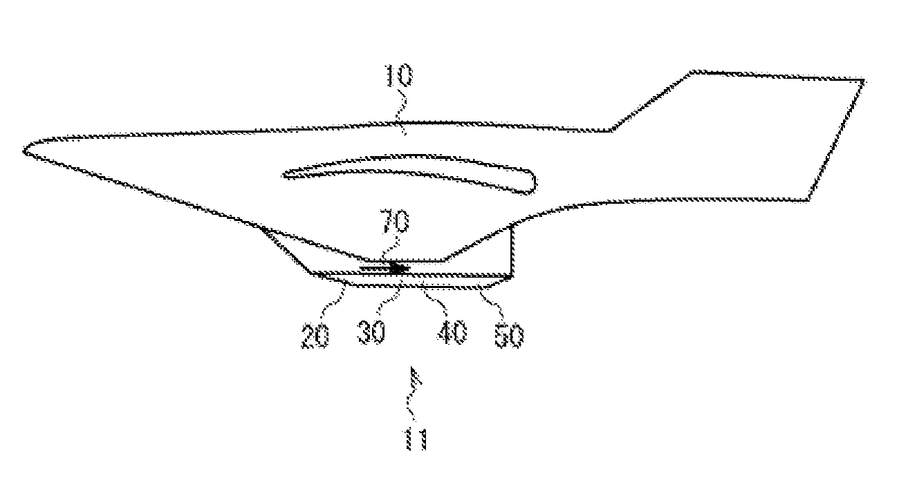
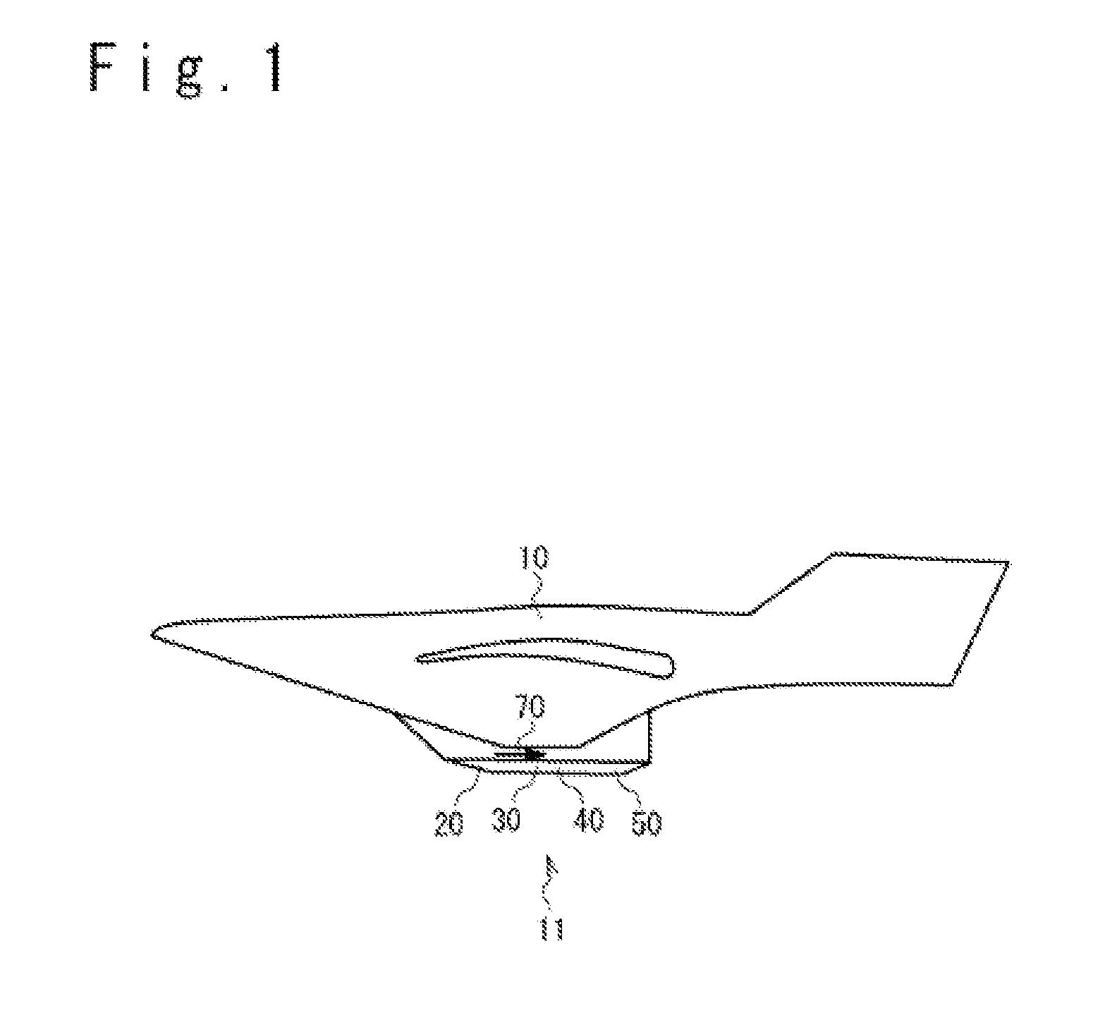
[0036]Configurations of the fuel supply system and the scramjet engine according to the present embodiment will be described. FIG. 1 is a schematic view showing a configuration example of an aircraft to which a scramjet engine according to this embodiment is applied. This aircraft includes an airframe 10 and a scramjet engine 11 included in the airframe 10. The scramjet engine 11 is an engine which generates a driving force by supersonic combustion, and includes a compression section 20, an injector 30, a combustion chamber 40, and a nozzle 50. The air compression section 20 compresses air introduced from the outside and generates a compressed air to supply to the combustion chamber 40. The injector 30 sprays a reformed fuel in an air current 70 of the compressed air, in the combustion chamber 40. In ...


PUM


Abstract

In order to stably use a catalyst for pyrolysis and supply a reformed fuel, the fuel supply system includes a fuel reforming section which pyrolyses a hydrocarbon system fuel by the heat of the combustion chamber to generate the reformed fuel. The fuel reforming section includes a preheat vaporization section provided on the combustion chamber, and a decomposition reaction section that is provided on the preheat vaporization section and includes the catalyst for pyrolysis. The preheat vaporization section heats the fuel, the decomposition reaction section pyrolyses the heated fuel to generate the reformed fuel, and the fuel reforming section supplies the reformed fuel to the combustion chamber. The reforming catalyst includes a zeolitic catalyst.

Description

INCORPORATION BY REFERENCE[0001]This patent application claims a priority on convention based on Japanese Patent Application No. 2013-015092. The disclosure thereof is incorporated herein by reference.TECHNICAL FIELD[0002]The present invention rerates to a scramjet engine which generates a driving force by supersonic combustion, and particularly to a fuel supply system of the scramjet engine.BACKGROUND ART[0003]In order to stabilize supersonic combustion using a fuel of hydrocarbon system, it is desirable to increase a rate of hydrocarbon with small carbon number in a fuel, and keep a distribution of the carbon number constant in the fuel. Also, since the hydrocarbon with small carbon number is a gas state at normal temperature, when the hydrocarbon with small carbon number is mounted on a fuel tank, Fuel on Board cannot be increased and supersonic combustion (supersonic flight) cannot be realized for long periods of time. Therefore, it is considered to mount hydrocarbon with large ...

Claims


Application Information

Patent Timeline
Patent Type & Authority Applications(United States)
IPC IPC(8): F02K9/68F02K7/14
CPCF02K9/68F02K7/14F05D2220/10F05D2240/35F02C7/22
Inventor SUZUKI, KENJIKUROYANAGI, ATSUSHIYASUTAKE, TOSHINOBU
Owner MITSUBISHI HEAVY IND LTD
Features
  • R&D
  • Intellectual Property
  • Life Sciences
  • Materials
  • Tech Scout
  • Unparalleled Data Quality
  • Higher Quality Content
  • 60% Fewer Hallucinations
Learn More