Solar cell module

Inactive Publication Date: 2014-07-31
PANASONIC INTELLECTUAL PROPERTY MANAGEMENT CO LTD
View PDF3 Cites 2 Cited by
  • Summary
  • Abstract
  • Description
  • Claims
  • Application Information

AI Technical Summary

Benefits of technology

[0009]According to the soar cell module above, it is possibl

Problems solved by technology

For this reason, if the back surface protection member contains carbon black, there arises a problem that the b

Method used


Image

  • Solar cell module
  • Solar cell module
  • Solar cell module

Examples


Example

[0015]Hereinafter, embodiments are described. Note that the following embodiments are for illustrative purposes only. The invention is by no means limited to the following embodiments.

[0016]In addition, in the drawings referenced in the embodiments and the like, constituents having substantially the same function are designated by the same reference numerals. Moreover, the drawings referenced in the embodiments and the like are schematic ones, and the dimension ratios and the like of objects depicted in the drawings may be different from the dimension ratios and the like of the actual ones. The dimension ratio and the like of an object may differ between the drawings. The specific dimension ratio and the like of every object should be determined with the following explanation taken into consideration.

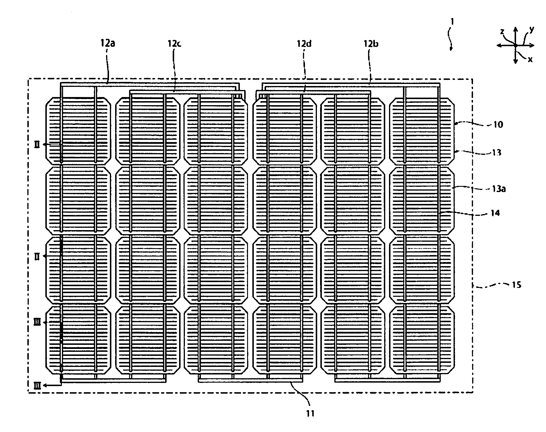
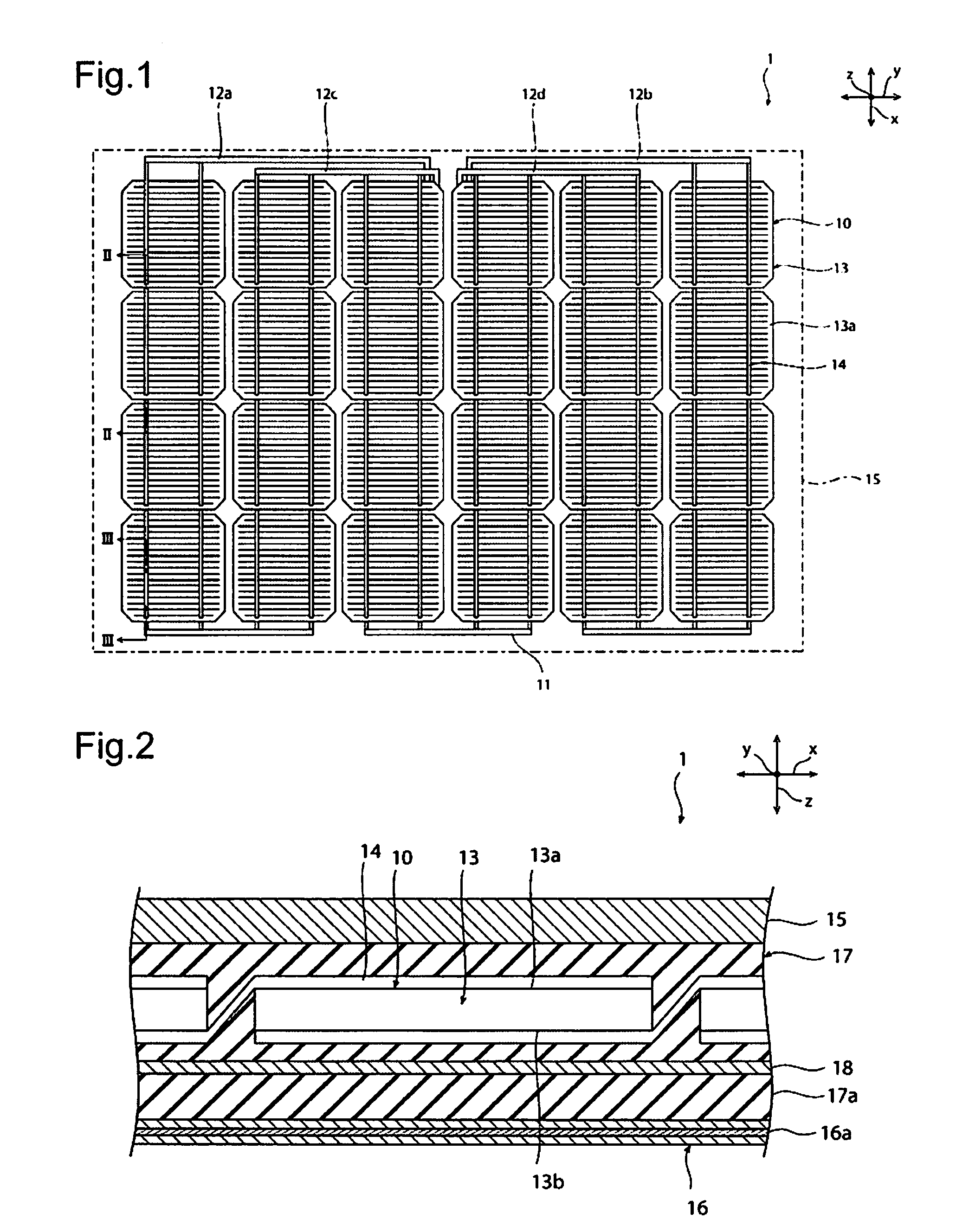
[0017]As illustrated in FIGS. 1 and 2, solar cell module 1 includes solar cell strings 10. Solar cell strings 10 are arranged at certain intervals in Y axis direction. Solar cell string...


PUM


Abstract

An absorption layer is provided on surface side of a solar cell, and is configured to absorb light in a wavelength range of 400 nm or more and below 700 nm and to transmit light in a wavelength range of 700 nm or more and 1200 nm or less. A first reflection layer is provided at one side of the absorption layer, which is an opposite side to the solar cell, and is configured to reflect the light in the wavelength range of 700 nm or more and 1200 nm or less. A filler layer is provided between the absorption layer and the reflection layer, and is configured to transmit light in the wavelength range of 400 nm or more and below 700 nm and to transmit light in a wavelength range of 700 nm or more and below 1200 nm.

Description

CROSS REFERENCE TO RELATED APPLICATIONS[0001]This application is a continuation application of International Application No. PCT / JP2012 / 061104, filed on Apr. 25, 2012, entitled “SOLAR CELL MODULE”, which claims priority based on Article 8 of Patent Cooperation Treaty from prior Japanese Patent Application No. 2011-264467, filed on Dec. 2, 2011, the entire contents of which are incorporated herein by reference.BACKGROUND[0002]The invention relates to a solar cell module.[0003]There has been conventionally known a solar cell module including solar cells arrayed in a filler layer filled between a light-receiving surface protection member and a back surface protection member. For example, in the case of a crystalline silicon solar cell, the color tone of the solar cells is black color in general. Accordingly, it is preferable that the back surface protection member of the solar cell module have a black color tone in order not to impair the aesthetic appearance of the solar cell module. ...

Claims


Application Information

Patent Timeline
IPC IPC(8): H01L31/052
CPCH01L31/0527Y02E10/52H01L31/048H01L31/0547H01L31/02013
Inventor YAMADA, HIROYUKINISHIDA, TAKAHIKO
Owner PANASONIC INTELLECTUAL PROPERTY MANAGEMENT CO LTD
Why Eureka
Try Eureka