
Kite for a system for extracting energy from the wind

a technology of energy extraction and kite, which is applied in the direction of toy aircraft, electric generator control, machines/engines, etc., can solve the problems of less than optimal system energy extraction system tension, power consumption, and static kite on the end of a rope that can only produce lift relative to the actual wind speed, etc., to achieve high tension, efficient flow, and increase the effect of system power outpu

Active Publication Date: 2014-07-31
KITE POWER SYST LTD
View PDF22 Cites 10 Cited by
  • Summary
  • Abstract
  • Description
  • Claims
  • Application Information

AI Technical Summary

Benefits of technology

The patent describes a system for flying a kite in a loop or spiral pattern to increase power output. The asymmetry of the kite's design allows it to orient itself to achieve high tension in the tether and maximize power output. This closed loop trajectory can be efficiently flown in a circle or spiral pattern, and the wing is shaped accordingly to achieve optimal performance.

Problems solved by technology

A static kite on the end of a rope can only produce lift relative to the actual wind speed.
If the kite moves away from the centre of the wind, in either azimuth or elevation, the amount of tension it can generate in the tether may be less than optimum for the system for extracting the energy from the wind.
However, when following a figure-of-eight flight pattern, regular large steering actions are required, which consumes power and destabilises the kite.
However, the physical size of the kite means that the speeds of the wing tips are quite different in a circular or helical flight path, which makes the design of the kite difficult.

Method used


Image

  • Kite for a system for extracting energy from the wind
  • Kite for a system for extracting energy from the wind
  • Kite for a system for extracting energy from the wind

Examples


Embodiment Construction

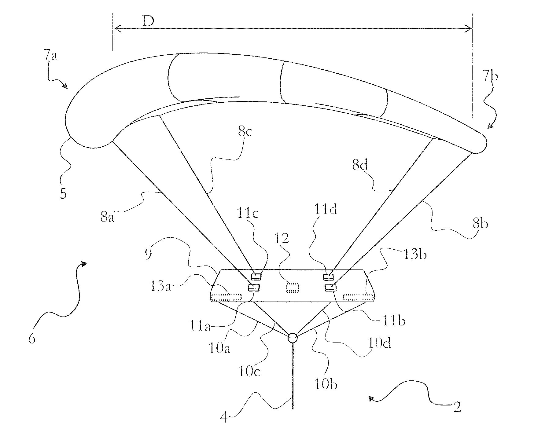
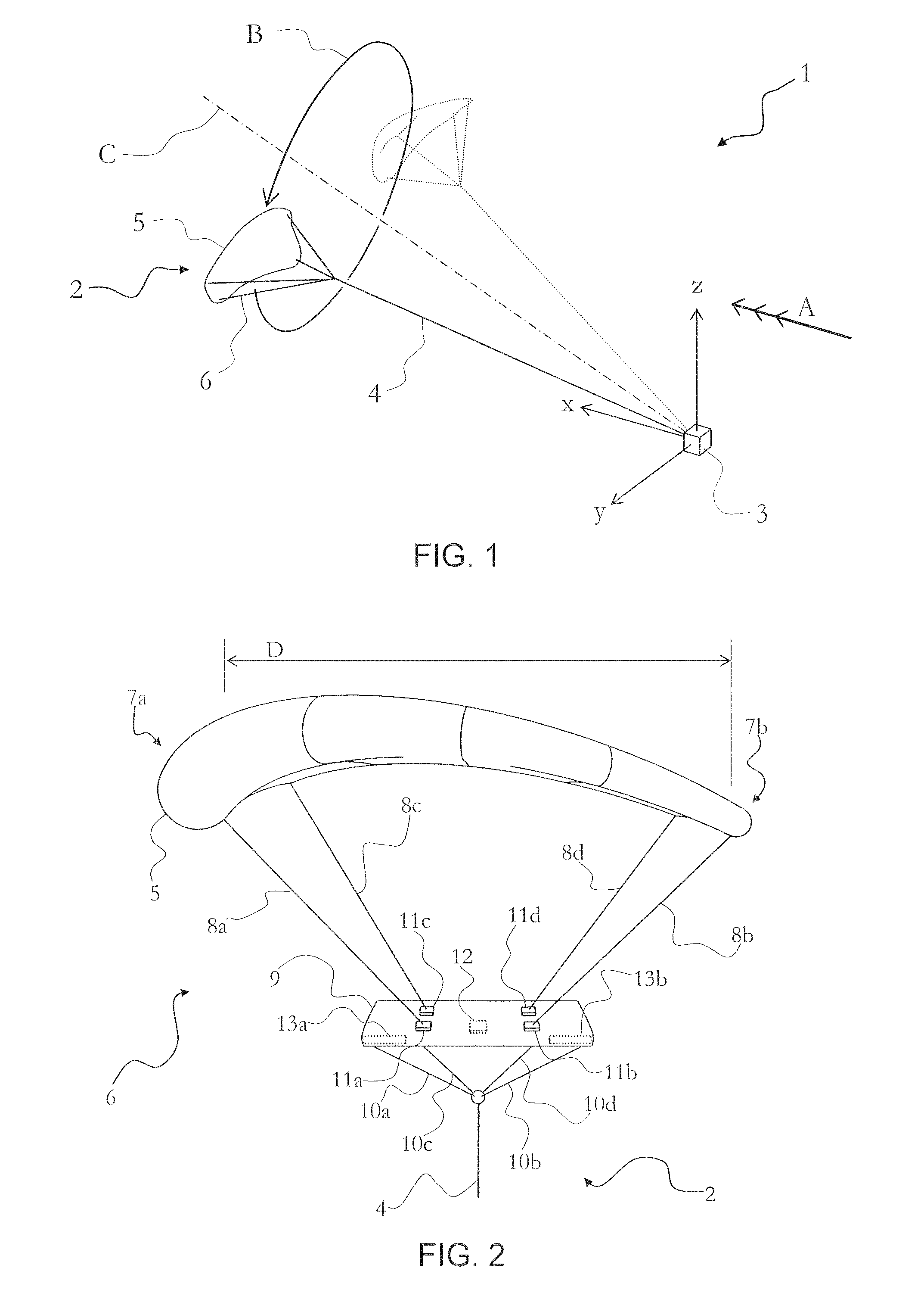
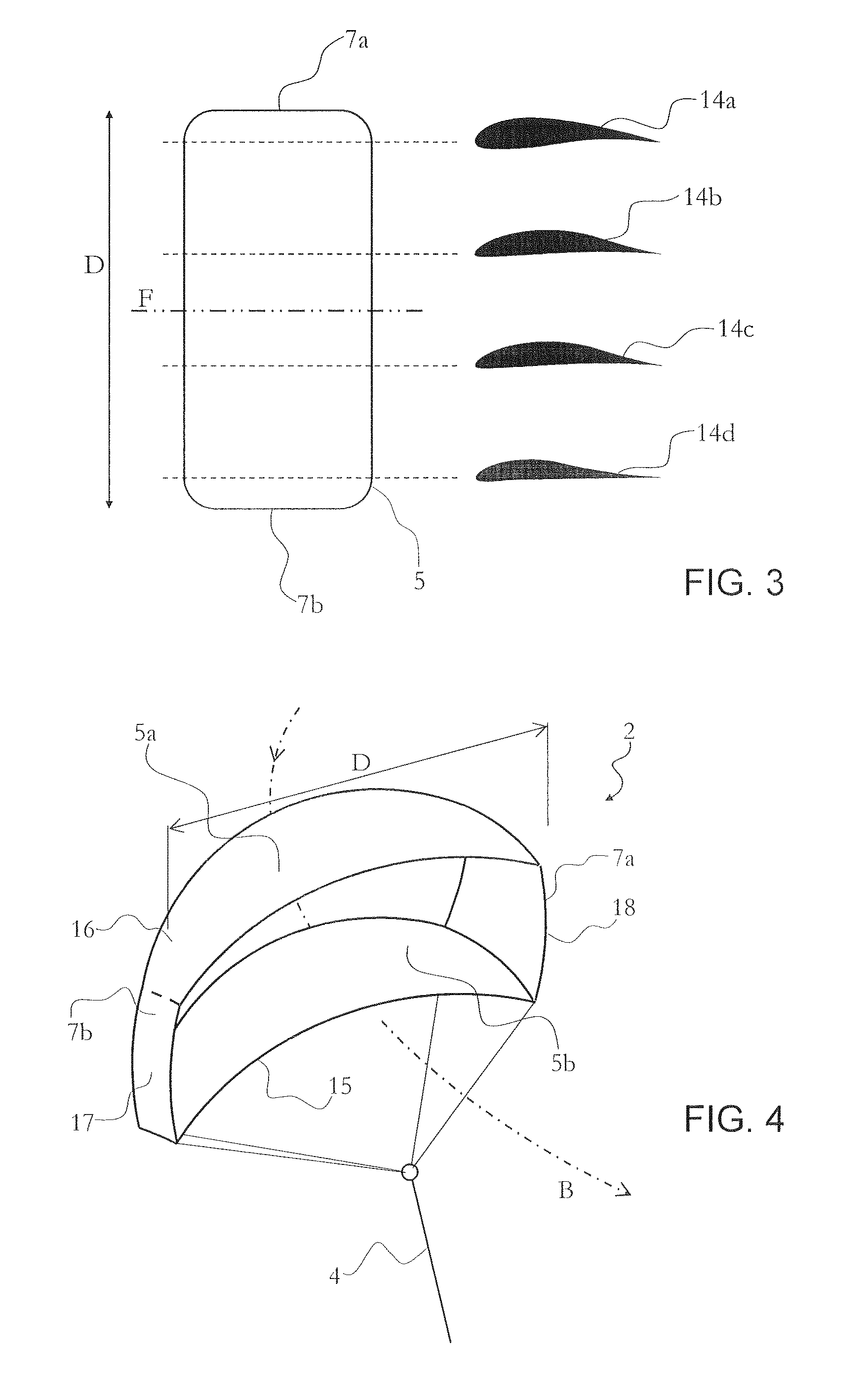
[0032]With reference to FIG. 1, there is provided a system 1 for extracting energy from the wind comprising a kite 2, a base unit 3 and a tether 4 tethering said kite 2 to the base unit 3. The kite 2 comprises a body forming at least one wing 5 for generating lift. According to the invention, the wing 5 of the kite is asymmetric in a spanwise direction. The asymmetry along the span of the wing may be provided to improve the efficiency of the system, as will be described in more detail below. The tether 4 is connected to the kite 2 and moves with the kite. In other words, the tether connected to the kite moves up and down in elevation and from left to right in azimuth as the kite flies across the wind. The kite 2 also comprises a support and control arrangement 6 for connecting the wing to the tether and for controlling the flight path of the kite, as will be described in more detail with respect to FIG. 2.

[0033]For the purpose of orientation, a set of right handed Cartesian axes (x,...


PUM


Abstract

A kite for a system for extracting energy from the wind, the kite comprising: a body having a wing for providing lift; means for connecting the wing to a tether; and means for controlling the flight of the kite in the wind, wherein the wing is constructed with an asymmetry in a spanwise direction from a first end of the wing to a second end of the wing to provide the wing with a naturally asymmetric shape at least when in flight. The asymmetry may be provided to optimise the shape of the wing for a flight pattern in which one end of the wing has a higher speed than the other end of the wing. For example, the asymmetry may be optimised to allow the kite to follow a flight pattern resembling a circle or spiral, from the point of view of a base unit of the system.

Description

FIELD OF THE INVENTION[0001]The invention relates to the conversion of wind power to other forms of energy using kites.BACKGROUND OF THE INVENTION[0002]People have tried to harness wind energy for thousands of years. Lately, with fossil fuels running out, techniques for converting the energy in the wind to other forms of energy and particularly electrical energy have become more popular. It is known to use wind turbines to extract the energy from the wind. It is also known to use kites to extract the energy from the wind. Kites can fly at an altitude where the wind speeds are more reliable than the wind speed at the height of the hub of a wind turbine. Whereas a wind turbine may have a height of 80 meters, kites can be flown at a typical height of 400 meters to 700 meters or higher. Kites are also easier to maintain and repair since they can be returned to ground level when not used, since the equipment for generating electric power are not required to be mounted at a height and sin...

Claims


Application Information

Patent Timeline
IPC IPC(8): B64C31/06F03D5/00F03D9/00
CPCY02E10/70Y02E10/728F03D11/04F03D5/00F03D5/005F05B2240/921B64C31/06F03D9/002F03D13/20F03D9/25Y02E10/72
Inventor HARDY, JOHN WILLIAM
Owner KITE POWER SYST LTD
Learn More