Power tool having a brushless motor and a control unit for controlling the brushless motor

Active Publication Date: 2014-07-31
MAKITA CORP
View PDF8 Cites 57 Cited by
  • Summary
  • Abstract
  • Description
  • Claims
  • Application Information

AI Technical Summary

Benefits of technology

[0007]In one embodiment, the control unit may control a current conduction angle and/or an advance angle supplied to the brushless motor so that a rotational speed or a conducting current of the brushless motor approaches or reaches a target value. This target value may be based or set at least in part on a battery voltage detected by the battery voltage detection unit. In this manner, it is possible to provide a power tool that performs in a manner consistent with similar power tools while reducing or preventing variations in drive characteristics between power tools that may be caused by manufacturing differences, such as, for example, errors in mounting the rotational position detection unit(s) proximal to the brushless motor.
[0008]In particular, in embodiments described in the present disclosure, the electric current driving the brushless motor may be controlled, and the current conduction angle and/or the advance angle may be controlled such that the rotational speed, the conducting current, and/or one or more related characteristics of the brushless motor approach(es) or reach(es) a target value. It is therefore possible to control the current conduction angle and/or the

Problems solved by technology

If the sensors that detect the motor rotational position are not placed consistently, or if other errors occur during the manufacturing process, the preset values of the conduction angle and/or the advance angle for the brushless motor may not be optimal for a particular power tool (eve

Method used


Image

  • Power tool having a brushless motor and a control unit for controlling the brushless motor
  • Power tool having a brushless motor and a control unit for controlling the brushless motor
  • Power tool having a brushless motor and a control unit for controlling the brushless motor

Examples


Embodiment Construction

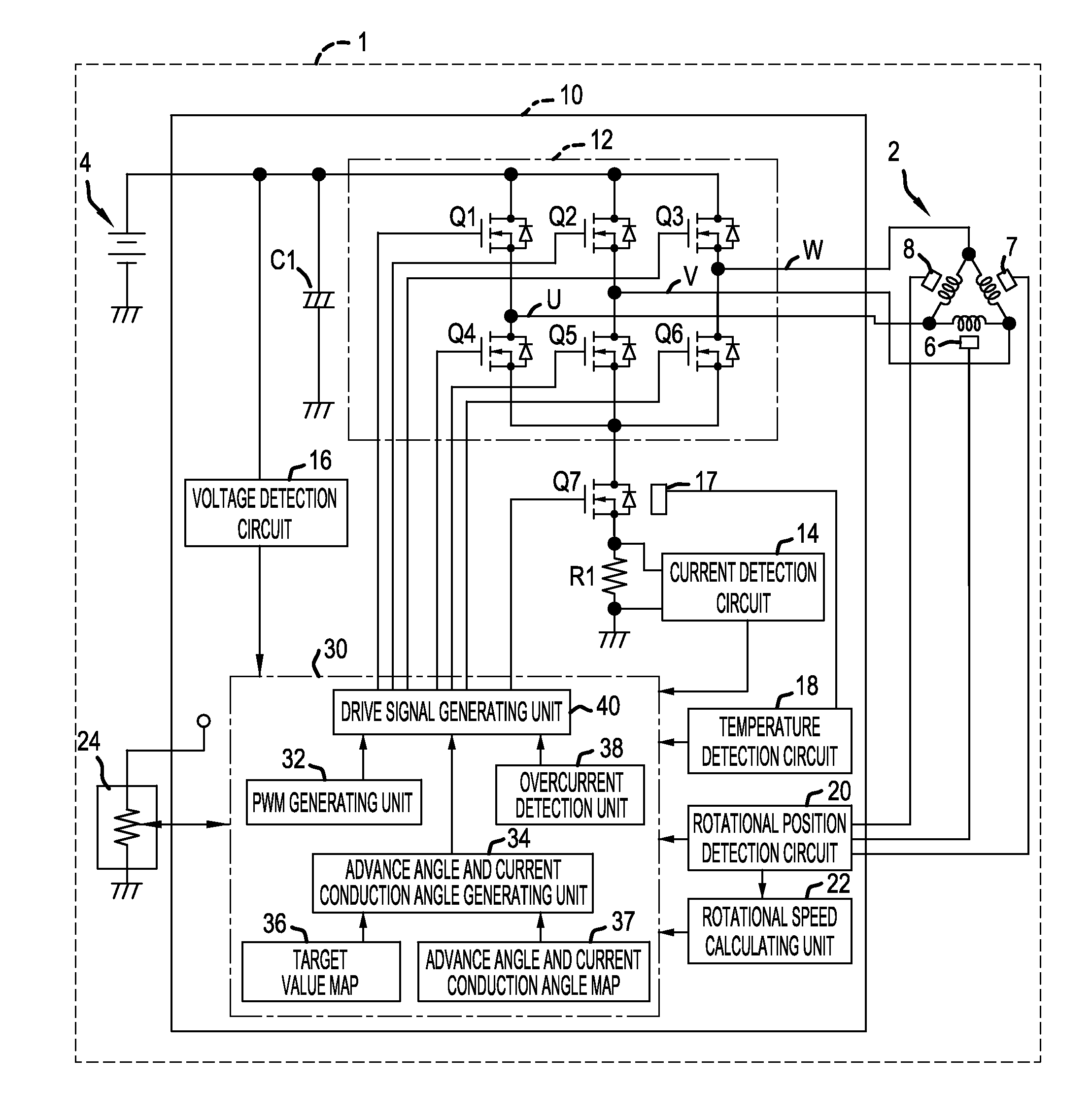
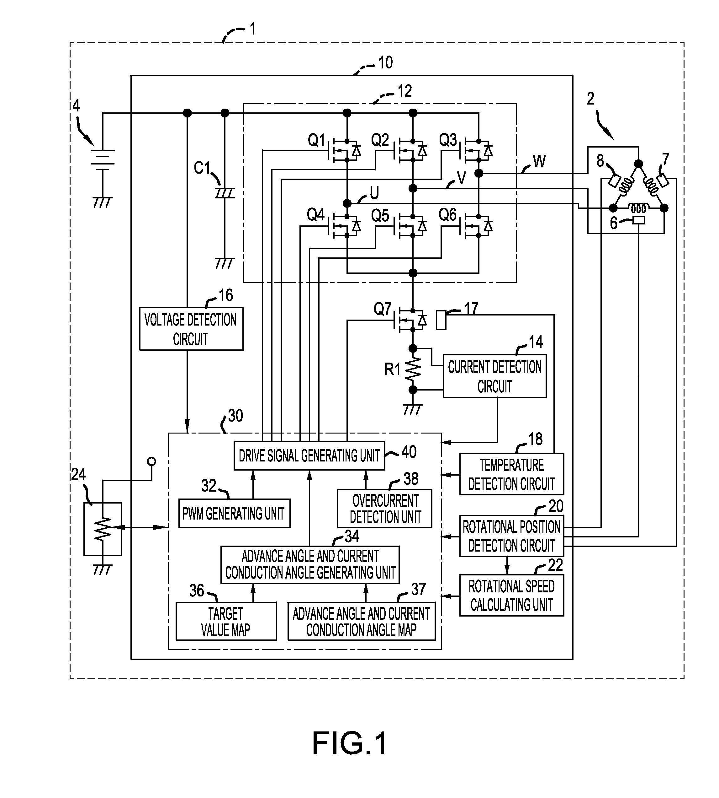
[0023]An exemplified embodiment as described in the present disclosure is explained below with reference to the drawings. In this embodiment, a motor drive apparatus drives a three-phase brushless motor 2 (hereinafter, simply referred to as a “motor”) that serves as a motive power source for a power tool 1, such as a rechargeable circular saw.

[0024]As shown in FIG. 1, a motor drive apparatus 10 comprises a power supply line and a ground line, each coupled to a battery 4, which comprises a direct current (DC) power supply. The power supply line of the motor drive apparatus 10 couples to a positive electrode of the battery 4. The ground line of the motor drive apparatus 10 couples to a negative electrode of the battery 4.

[0025]A switching circuit 12 is provided for controlling electric currents that flow to each of the three phases U, V, W of the motor 2. The switching circuit 12 is provided between the power supply line on the positive electrode side and the ground line on the negati...


PUM


Abstract

A power tool according to one aspect of one embodiment described in the disclosure includes a brushless motor, a battery voltage detection unit configured to detect a voltage of a battery that provides energy for driving the brushless motor, a rotational position detection unit configured to detect a rotational position of the brushless motor, and a control unit configured to control a drive output supplied to the brushless motor based at least in part on a signal from the rotational position detection unit. The control unit controls a current conduction angle and/or an advance angle supplied to the brushless motor so that, during control of the drive output to the brushless motor, a rotational speed or a conducting current of the brushless motor approaches or reaches a target value, the target value being based at least in part on a battery voltage detected by the battery voltage detection unit.

Description

CROSS-REFERENCE[0001]This application claims priority to Japanese patent application no. 2013-013427 filed on Jan. 28, 2013, the contents of which are fully incorporated herein by reference.TECHNICAL FIELD[0002]The present invention is generally directed to a power tool having a brushless motor as a motive power source, and, for example, to a power tool having a control unit for controlling a brushless motor power source based on detected conditions.BACKGROUND ART[0003]Power tools driven by brushless motors are known. In such power tools, the current conduction angle and the advance angle of the brushless motor are fixed or preset based on typical or expected operating conditions. Japanese Unexamined Patent Application Publication No. 2007-276042 (and its family member US 2009 / 0160373), for example, discloses a power tool having a brushless motor with a current conduction angle and an advance angle that are preset to fixed values in order to optimize drive characteristics of the bru...

Claims


Application Information

Patent Timeline
IPC IPC(8): H02P6/08B25F5/00
CPCH02P6/08H02P6/15H02P6/153
Inventor KATO, ITSUKUOMURA, MOTOHIRO
Owner MAKITA CORP
Why Eureka
Try Eureka