
Turbochargers

Active Publication Date: 2014-07-31
TOYOTA IND CORP
View PDF2 Cites 32 Cited by
  • Summary
  • Abstract
  • Description
  • Claims
  • Application Information

AI Technical Summary

Benefits of technology

The invention is about a heat shield for a turbine housing that reduces the amount of heat transferred to the housing. The heat shield is made up of a heat resistant plate that is placed in the turbine housing to block the transmission of heat. This reduces the energy loss of the fluid and the strain on the turbine's parts. The heat shield can be easily attached to the housing without needing any additional components. Overall, the invention helps improve the efficiency of the turbine.

Problems solved by technology

Forming the turbine housing by using a material having a very high heat resistance will result in an increase in the cost of the turbine housing.
Forming the turbine housing by using a material having a lower heat resistance and enhancing the cooling capacity of the turbine housing will result in an increase in loss of the energy of the exhaust gas.
This will result in the deterioration of intake efficiency, which means this structure is rather undesirable.

Method used


Image

  • Turbochargers
  • Turbochargers
  • Turbochargers

Examples


Embodiment Construction

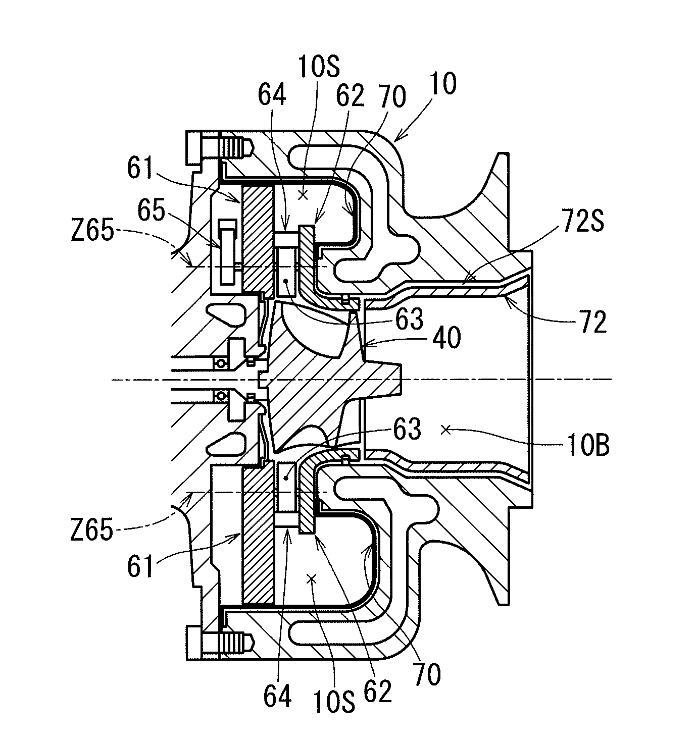
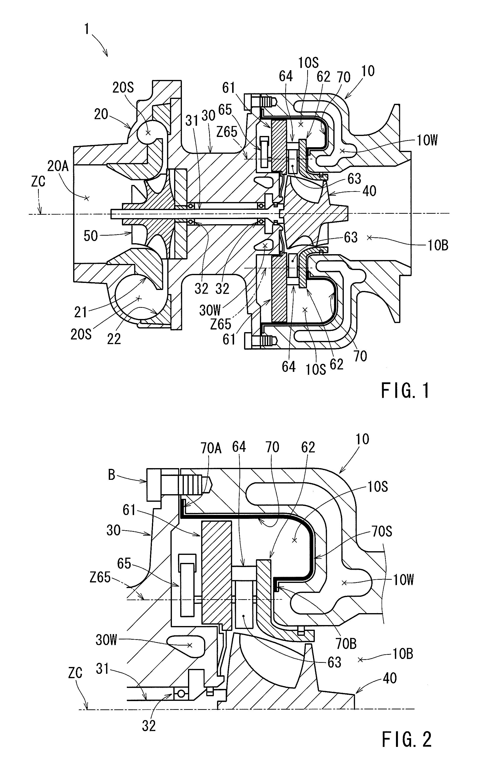
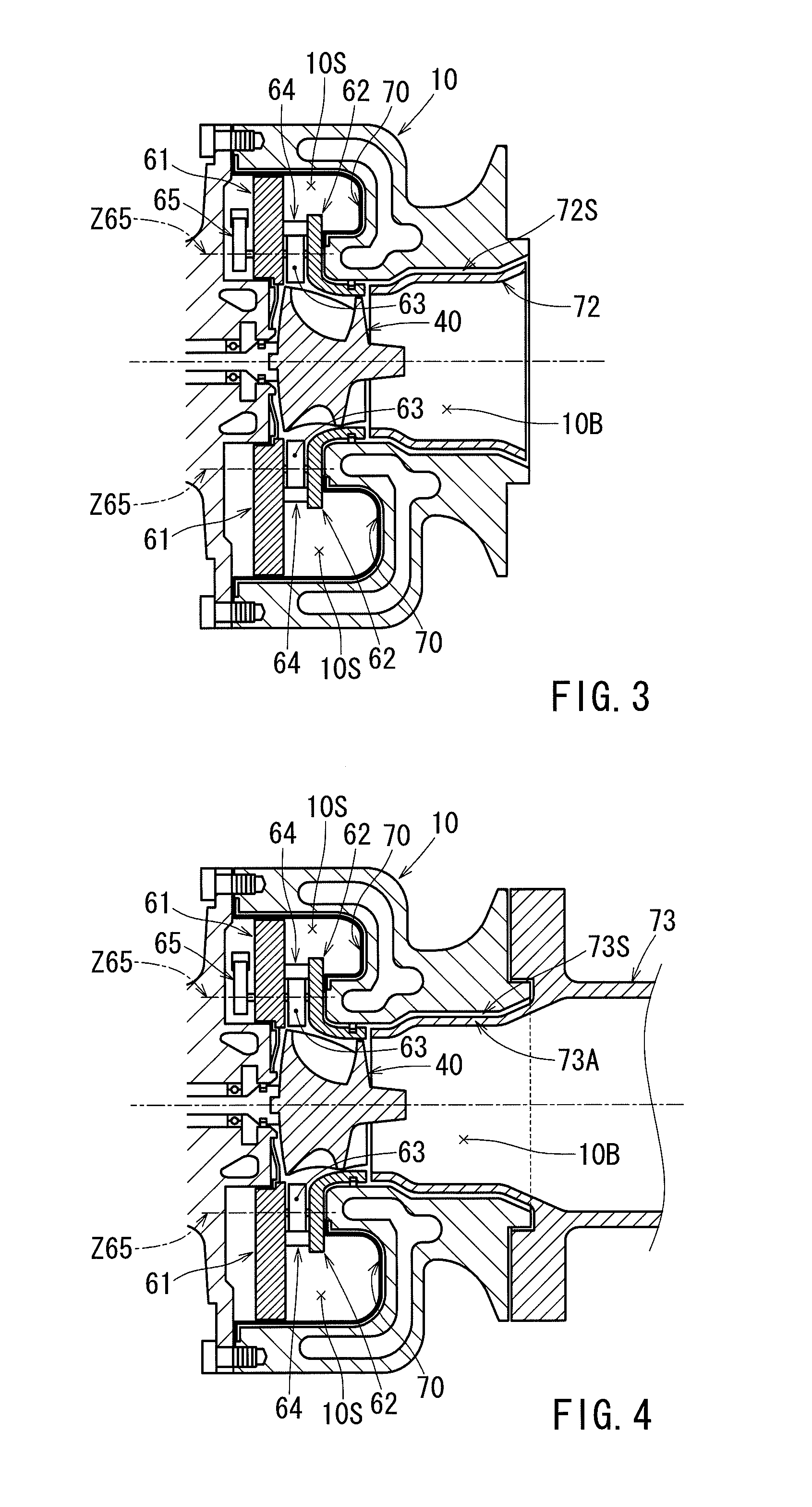
[0028]Each of the additional features and teachings disclosed above and below may be utilized separately or in conjunction with other features and teachings to provide improved turbochargers. Representative examples of the present invention, which utilize many of these additional features and teachings both separately and in conjunction with one another, will now be described in detail with reference to the attached drawings. This detailed description is merely intended to teach a person of ordinary skill in the art further details for practicing preferred aspects of the present teachings and is not intended to limit the scope of the invention. Only the claims define the scope of the claimed invention. Therefore, combinations of features and steps disclosed in the following detailed description may not be necessary to practice the invention in the broadest sense, and are instead taught merely to particularly describe representative examples of the invention. Moreover, various featur...


PUM


Abstract

Embodiments of the present invention may include a turbocharger having a turbine, a turbine housing, a variable valve, a first plate, a second plate and a heat shield member. The turbine housing accommodates the turbine and has a flow path. The variable valve rotates about each pivot member provided thereon, thereby adjusting the flow velocity of fluid guided from the flow path to the turbine. The first plate supports one end of each pivot member, and defines the flow path. The second plate supports the other end of each pivot member or the variable valves, and defines the flow path. The heat shield member covers a wall surface of the turbine housing, and defines the flow path.

Description

[0001]This application claims priority to Japanese patent application serial number 2013-14197, the contents of which are incorporated herein by reference.BACKGROUND OF THE INVENTION[0002]1. Field of the Invention[0003]Embodiments of the present invention relate to a turbocharger.[0004]2. Description of the Related Art[0005]A turbocharger is employed, for example, in an internal combustion engine mounted in a vehicle. In the conventional turbocharger, the energy of the exhaust gas of the internal combustion engine is recovered by a turbine. An impeller (compressor) connected to the turbine by a shaft is rotated by the recovered energy. Intake air is supercharged to the internal combustion engine by the rotating impeller. This helps to enhance the intake efficiency and to achieve an improvement in terms of output and fuel efficiency.[0006]A flow path for the exhaust gas is formed in a turbine housing accommodating the turbine. An exhaust gas at a very high temperature (e.g., 800° C. ...

Claims


Application Information

Patent Timeline
IPC IPC(8): F01D17/14F01D25/14
CPCF01D25/145F01D17/145F01D17/165F01D25/14F05D2220/40
Inventor UESUGI, TSUYOSHI
Owner TOYOTA IND CORP
Learn More