
Semiconductor package

a technology of semiconductors and packages, applied in the direction of semiconductor/solid-state device details, semiconductor devices, electrical apparatus, etc., can solve the problems of increasing the temperature affecting the efficiency of the semiconductor chip, and generating a larger quantity of heat in the semiconductor package. , to achieve the effect of preventing an excessive temperature increase of the semiconductor chip

Active Publication Date: 2014-08-07
SAMSUNG ELECTRONICS CO LTD
View PDF10 Cites 9 Cited by
  • Summary
  • Abstract
  • Description
  • Claims
  • Application Information

AI Technical Summary

Benefits of technology

The patent describes a way to prevent computer chips from overheating when they are exposed to high power. This is done by using a heat capacitor that can absorb the excess heat generated by the chip, reducing the risk of damage.

Problems solved by technology

Higher performance of a high density semiconductor package operating at higher speed necessarily generates a larger quantity of heat in the semiconductor package.
However, the heat transfer rate for heat dissipation by heat conduction using the metal that comprises the heat spreader is often inadequate.
In the same way, the heat transfer rate for heat dissipation by heat convection using a convection fluid is also often insufficient regardless of the degree of natural and forced convection.
These devices also typically require high average power due to their high performance design.
However, the large quantity of substantially instantaneous heat that is commonly generated from the semiconductor package when an instantaneous driving power is applied cannot be sufficiently dissipated through the conventional thermal dissipation system.
However, such an automatic power shut-off to the IC chip necessarily decreases the performance of the IC chip.
Thus, the IC chip is forced to operate below the maximal performance and driving specifications.
As a result, the average performance of the semiconductor package having the IC chip may decrease due to the automatic power shut-off under excessive heat conditions.

Method used


Image

  • Semiconductor package
  • Semiconductor package
  • Semiconductor package

Examples


Embodiment Construction

[0041]Various embodiments in accordance with the inventive concepts, will be described more fully hereinafter with reference to the accompanying drawings, in which some embodiments are shown. The present inventive concepts may, however, be embodied in many different forms and should not be construed as limited to the embodiments set forth herein. Rather, these embodiments are provided so that this disclosure will be thorough and complete, and will fully convey the scope of the present inventive concepts to those skilled in the art. In the drawings, the sizes and relative sizes of layers and regions may be exaggerated for clarity.

[0042]It will be understood that when an element or layer is referred to as being “on,”“connected to” or “coupled to” another element or layer, it can be directly on, connected or coupled to the other element or layer or intervening elements or layers may be present. In contrast, when an element is referred to as being “directly on,”“directly connected to” o...


PUM


Abstract

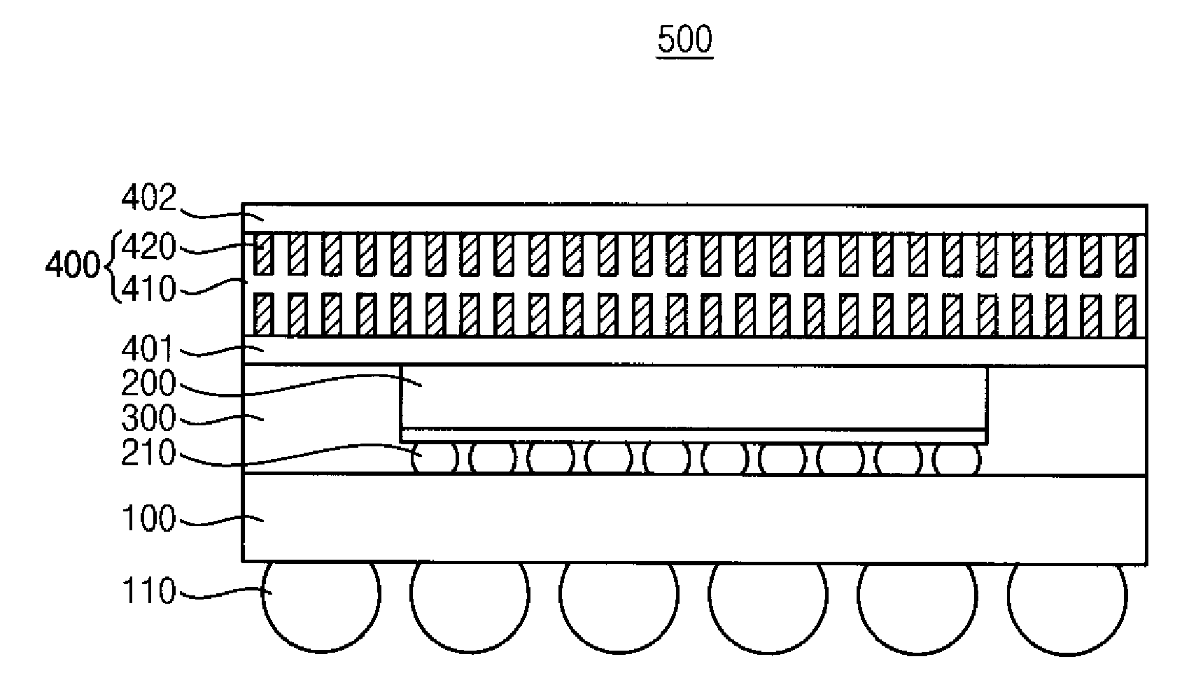
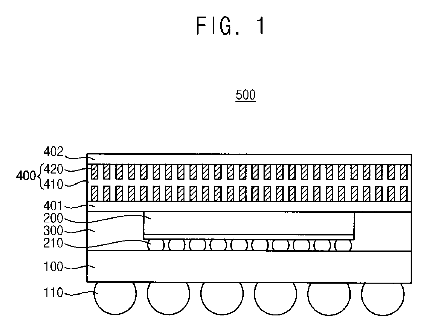
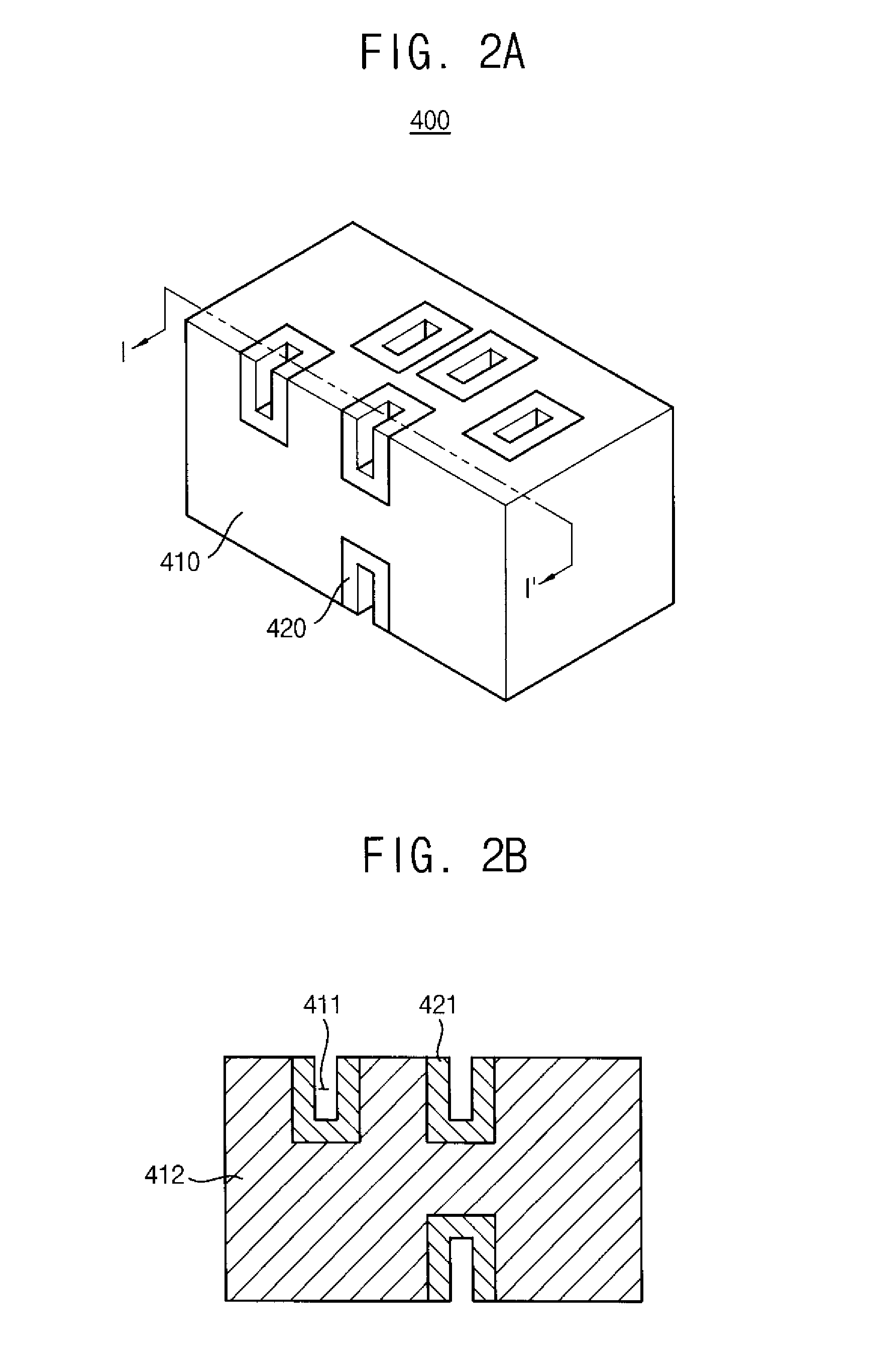
A semiconductor package and a method of manufacturing the same are disclosed, wherein the semiconductor package includes a circuit board, a semiconductor chip mounted on the circuit board, an encapsulant positioned on the circuit board and encapsulating the semiconductor chip to the circuit board, and a thermal dissipating member positioned on the encapsulant and having a heat spreader that dissipates a driving heat from the semiconductor chip and a heat capacitor that absorbs excess driving heat that exceeds a heat transfer capability of the heat spreader, such that when a high power is applied to the package, the excess heat is absorbed into the heat capacitor as a latent heat and thus the semiconductor chip is protected from an excessive temperature increase caused by the excess heat, thereby increasing a critical time and performance duration time of the semiconductor package.

Description

CROSS-REFERENCE TO RELATED APPLICATIONS[0001]This application claims the benefit of Korean Patent Application No. 10-2013-0012923 filed on Feb. 5, 2013 in the Korean Intellectual Property Office, the disclosure of which is incorporated herein in its entirety by reference.BACKGROUND[0002]1. Field[0003]Embodiments of the inventive concepts relate to a semiconductor package and a method of manufacturing the same, and more particularly, to a semiconductor package having a heat spreader and a thermal capacitor and a method of manufacturing the same.[0004]2. Description of the Related Art[0005]As electronic devices have become more highly integrated and designed to deliver higher performance, the semiconductor package is also increasingly being manufactured to have a smaller size and higher density. Higher performance of a high density semiconductor package operating at higher speed necessarily generates a larger quantity of heat in the semiconductor package. Thus, sufficient thermal diss...

Claims


Application Information

Patent Timeline
Patent Type & Authority Applications(United States)
IPC IPC(8): H01L23/367H01L23/373
CPCH01L23/3733H01L23/367H01L23/3128H01L23/3736H01L23/4275H01L2224/16225H01L2924/15311H01L23/34H01L23/36
Inventor IM, YUN- HYOEKPARK, KYOLLEE, HEE-SEOK
Owner SAMSUNG ELECTRONICS CO LTD
Learn More