

System for twisting cables in a wind turbine tower
- Summary
- Abstract
- Description
- Claims
- Application Information
AI Technical Summary
Benefits of technology
Problems solved by technology
Method used
Image

Examples
Embodiment Construction
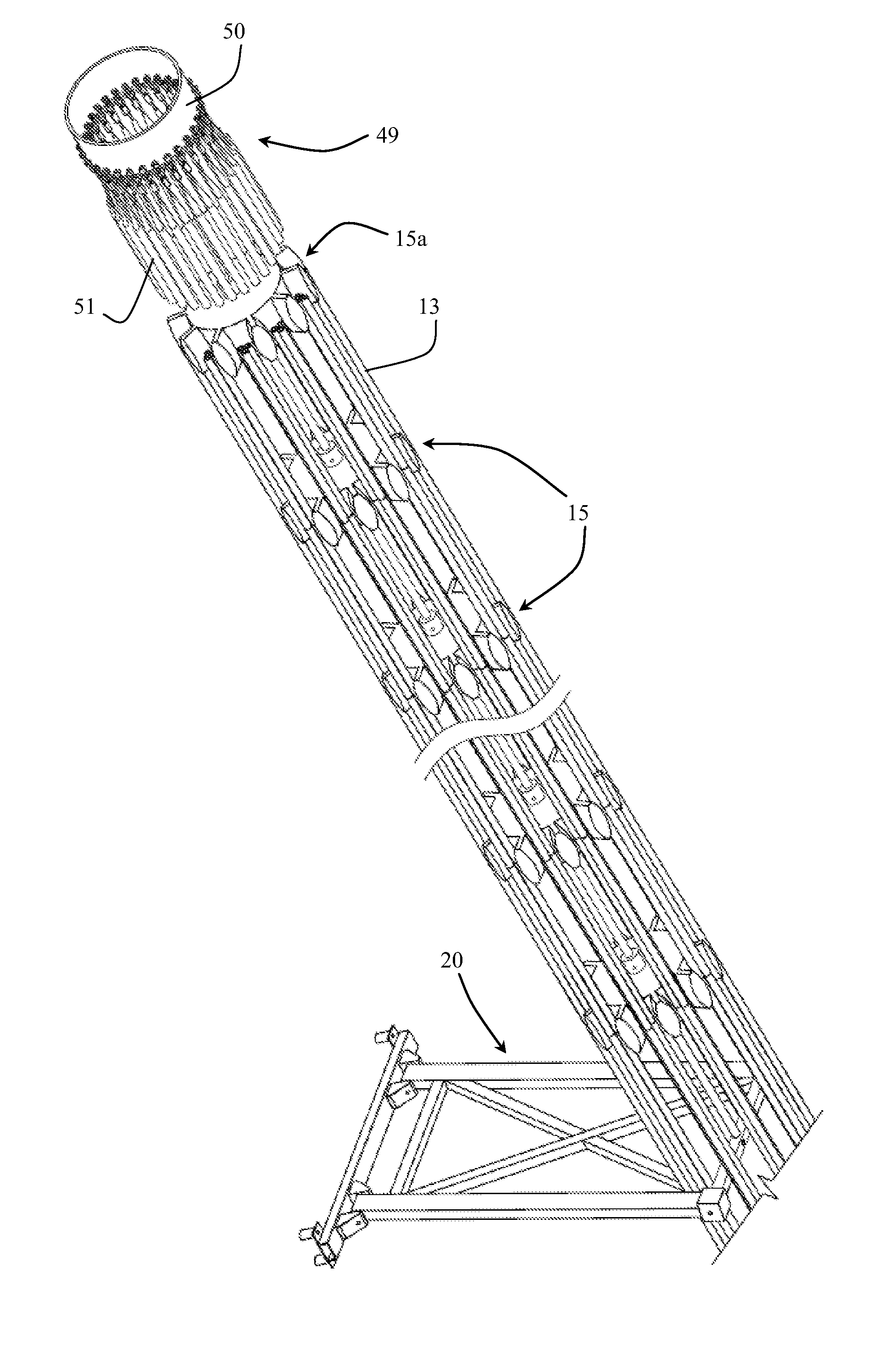
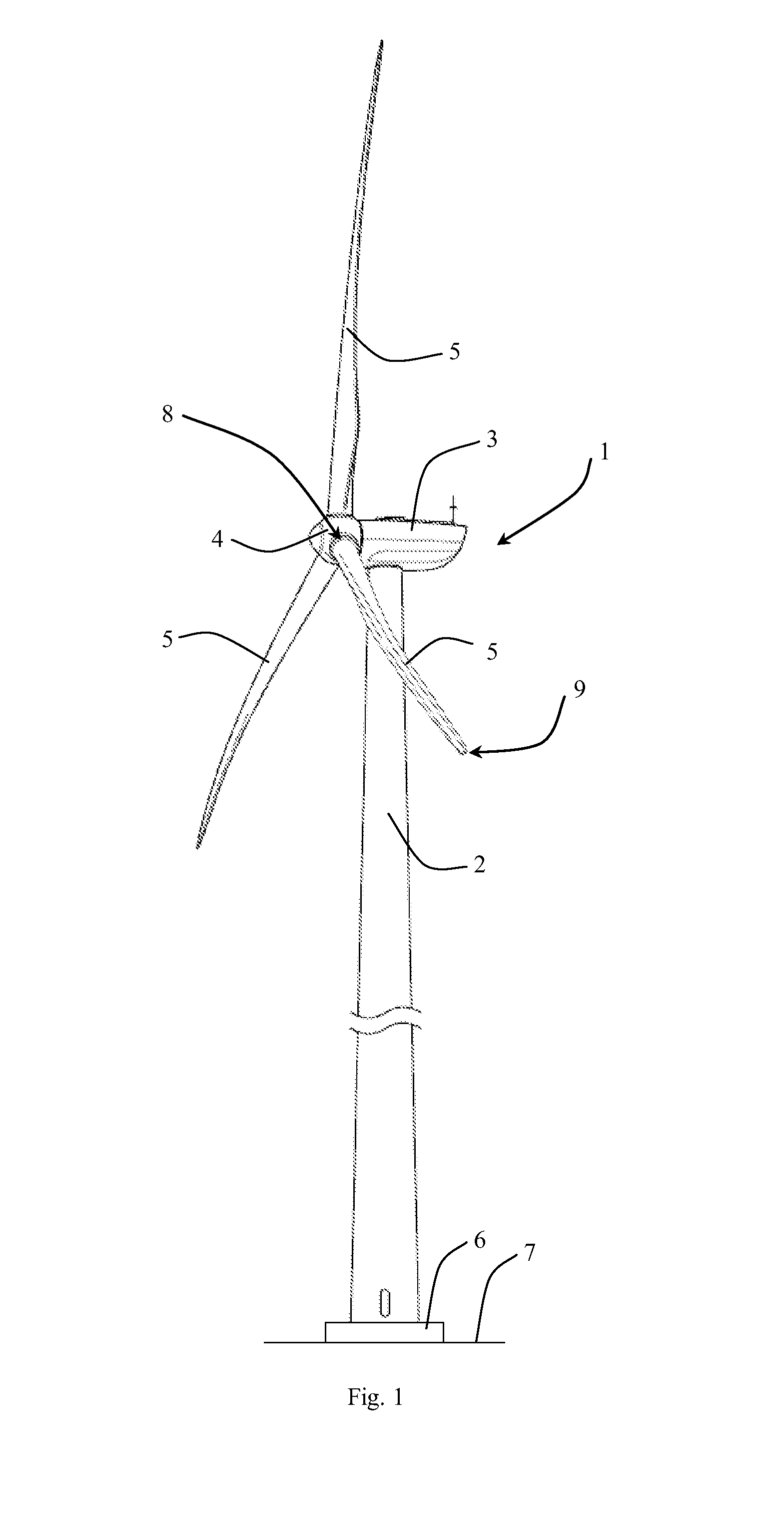
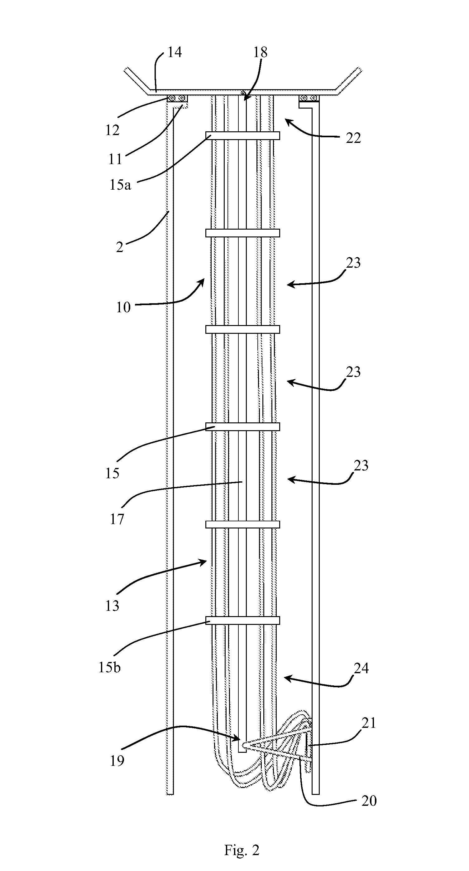
[0021]An object of the invention is achieved by a wind turbine, characterized in that
[0022]the suspension element is a torsion element comprising a first end facing the nacelle and a second end facing the bottom of the wind turbine tower which both have a common center axis, wherein the first end is configured to twist relative to the second end due to its torsion properties when torque is applied to the first end, and wherein the first end is configured to return to its initial position when the torque is removed.
[0023]This provides a cable twisting system capable of rotating the individual cable spacing plates in a more uniform manner when the nacelle is yawing. The configuration allows the upwards movement of the cable spacing plates, which is caused by the torque applied by the nacelle, to start at the uppermost cable spacing plate, unlike a traditional cable twisting system where the upwards movement starts at the lowermost cable spacing plate. The angular rotation of the cable...
PUM
 Abstract
Description
Claims
Application Information