
Image reporting method

a technology of image and reporting method, applied in the field of image interpretation, can solve the problems of compounding the specialist's fatigue and vulnerability to oversight, and the coordinate system provided by the cad system cannot be used to guide a biopsy needle,

Active Publication Date: 2014-08-07
MOEHRLE ARMIN +1
View PDF5 Cites 52 Cited by
  • Summary
  • Abstract
  • Description
  • Claims
  • Application Information

AI Technical Summary

Benefits of technology

The patent describes an image reporting method and apparatus that can automatically analyze and report on images of a sample structure. The method involves retrieving an image representation of the sample structure, mapping a generic structure to the sample structure, identifying regions of interest within the sample structure, and associating annotations with the regions of interest. The method can also automatically generate a description of the region of interest based on the annotation and spatial coordinates. The technical effects of this patent include improved efficiency and accuracy in image reporting, as well as improved consistency and reliability of the reporting process.

Problems solved by technology

Unfortunately, these prior art systems are limited to describing the location of the visual phenomena within the image file.
By manner of illustration, the coordinate system provided by the CAD system cannot be used to guide a biopsy needle because it fails to identify the relative position within the organ or sample structure.
While such inconveniences may pose a seemingly insignificant risk of error, a typical specialist must interpret a substantial amount of such images in short periods of time, which further compounds the specialist's fatigue and vulnerability to oversights.
Currently existing image reporting mechanisms do not take full advantage of knowledge representations to assist interpretation while automating reporting.
In particular, currently existing systems are not fully integrated with knowledge representations to provide seamless and effortless reference to knowledge representations during articulation of findings.
While there is a general lack of such brokering service between the entities of most domains, there is an even greater deficiency in the available means to promote common agreements between terminologies, especially in image reporting applications.
Furthermore, due to the lack of more streamlined agreements between knowledge representations in image reporting, currently existing systems also lack means for automatically tracking the development of specific and related cases for inconsistencies or errors so that the knowledge representations may be updated to provide more accurate information in subsequent cases.

Method used


Image

  • Image reporting method
  • Image reporting method
  • Image reporting method

Examples


Embodiment Construction

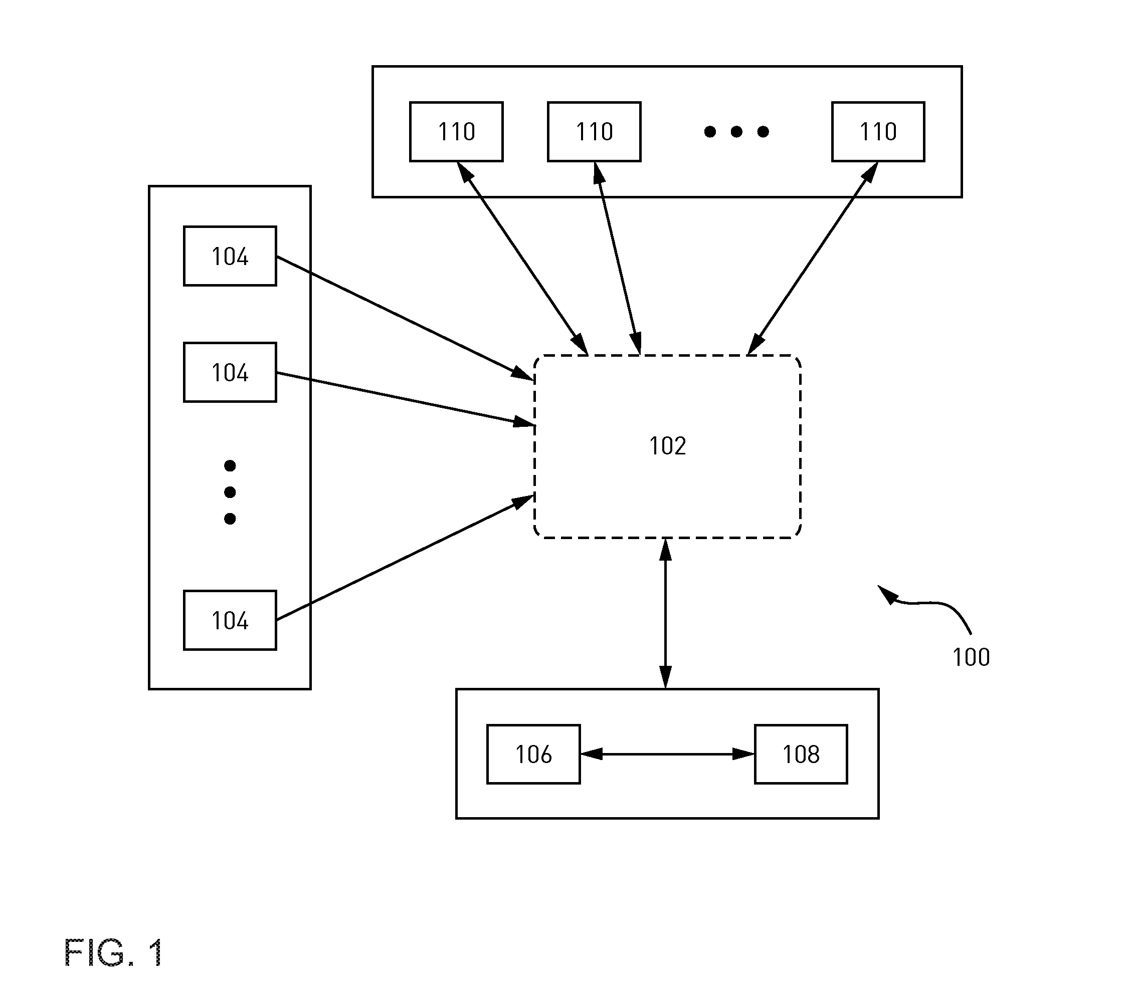
[0046]Referring now to FIG. 1, an exemplary system 100 within which an image interpretation and reporting method may be integrated is provided. As shown, the system 100 may include a central network 102 by which different components of the system 100 may communicate. For example, the network 102 may take the form of a wired and / or wireless local area network (LAN), a wide area network (WAN), such as the Internet, a wireless local area network (WLAN), a storage or server area network (SAN), and the like. The system 100 may also include image capture devices 104 configured to capture or generate two-dimensional and / or three-dimensional images. In medical imaging, for example, the image capture devices 104 may include one or more of a mammography device, a computed tomography (CT) device, an ultrasound device, an X-ray device, a fluoroscopy device, a film printer, a film digitizer, and the like. One or more images of a sample structure captured by the image capture devices 104 may be t...


PUM


Abstract

An image reporting method is provided. The image reporting method comprises the steps of retrieving an image representation of a sample structure from an image source; mapping a generic structure to the sample structure, the generic structure being related to the sample structure; determining a region of interest within the sample structure based on content of the image representation of the sample structure; providing a focused set of representations of diagnostic knowledge which is contextually appropriate to the region of interest and prompting the user to select at least one diagnostic finding from the focused set of knowledge representation or by entering free-form text; and generating a diagnostic report based on the selections and free-form text entries.

Description

FIELD OF THE DISCLOSURE[0001]The present disclosure generally relates to image interpretation, and more particularly, to systems and methods for generating image reports.BACKGROUND OF THE DISCLOSURE[0002]In current image interpretation practice, such as diagnostic radiology, a specialist trained in interpreting images and recognizing abnormalities may look at an image or an image sequence on an image display and report any visual findings by dictating or typing the findings into a report template. The dictating or typing usually includes a narration of the finding, a description about the location of the visual phenomena, abnormality, or region of interest within the images being reported on. The recipient of the report is often left to further analyze the contents of the narrative text report without having easy access to the underlying image. More particularly, in current reporting practice, there is no link between the specific location in the image and the finding associated wit...

Claims


Application Information

Patent Timeline
Patent Type & Authority Applications(United States)
IPC IPC(8): G06T7/00
CPCG06T7/0014G06T2207/10008G06T2207/10081G06T2207/10116G06T2207/30068G16H15/00G16H30/20G16H50/20G16H50/70
Inventor MOEHRLE, ARMINCLARK, CRANDON F.
Owner MOEHRLE ARMIN
Learn More