
Segmented-coil manufacturing method, segmented-coil manufacturing device, and segmented coil manufactured using the method and the device

a manufacturing method and segment coil technology, applied in the direction of magnets, electromagnets, magnetic bodies, etc., can solve the problems of high processing methods and large size of motors, and achieve the reduction of segment coil cost, short cycle time, and reduced forming steps

Active Publication Date: 2014-08-14
TOYOTA JIDOSHA KK +1
View PDF3 Cites 13 Cited by
  • Summary
  • Abstract
  • Description
  • Claims
  • Application Information

AI Technical Summary

Benefits of technology

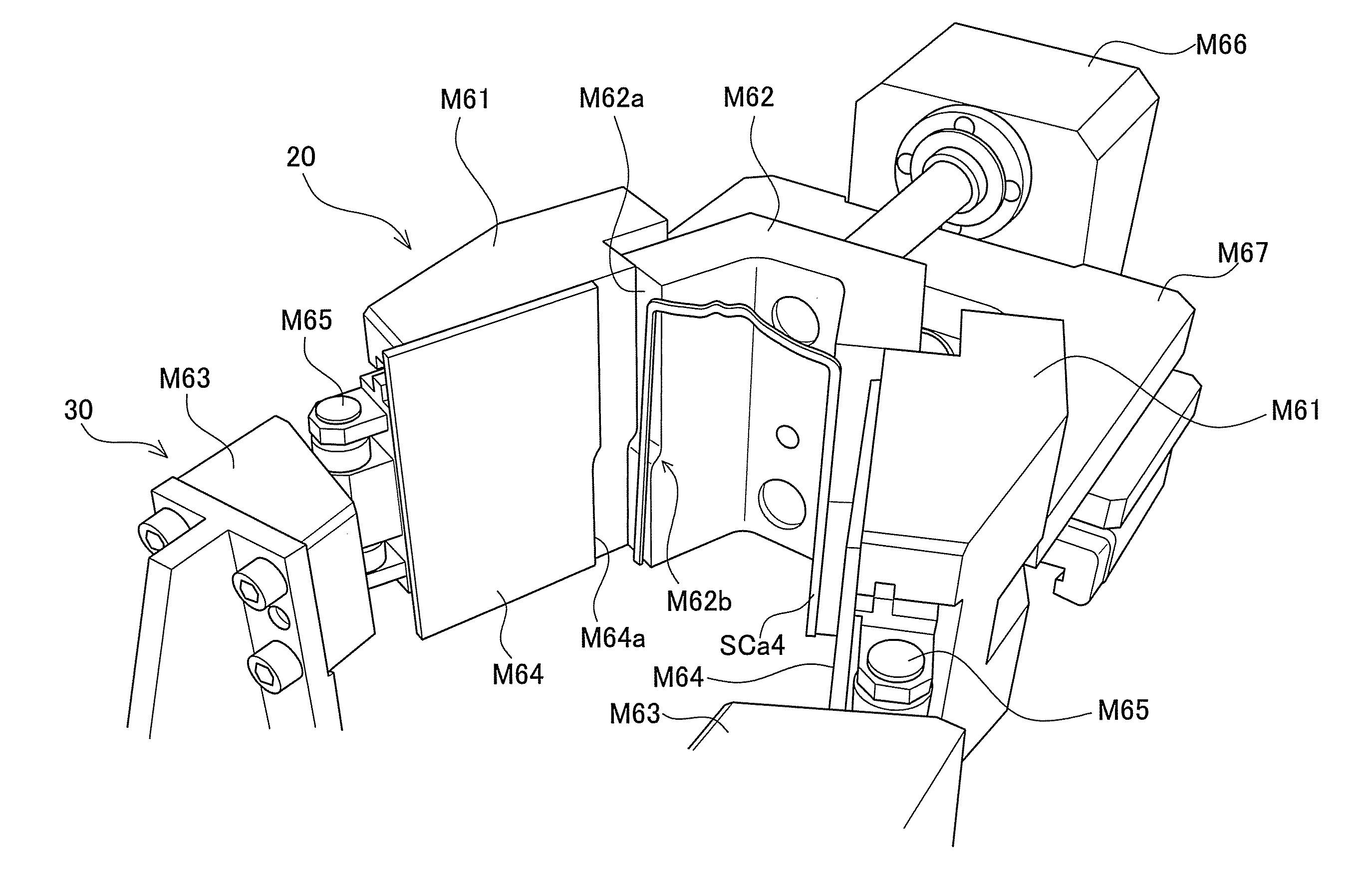
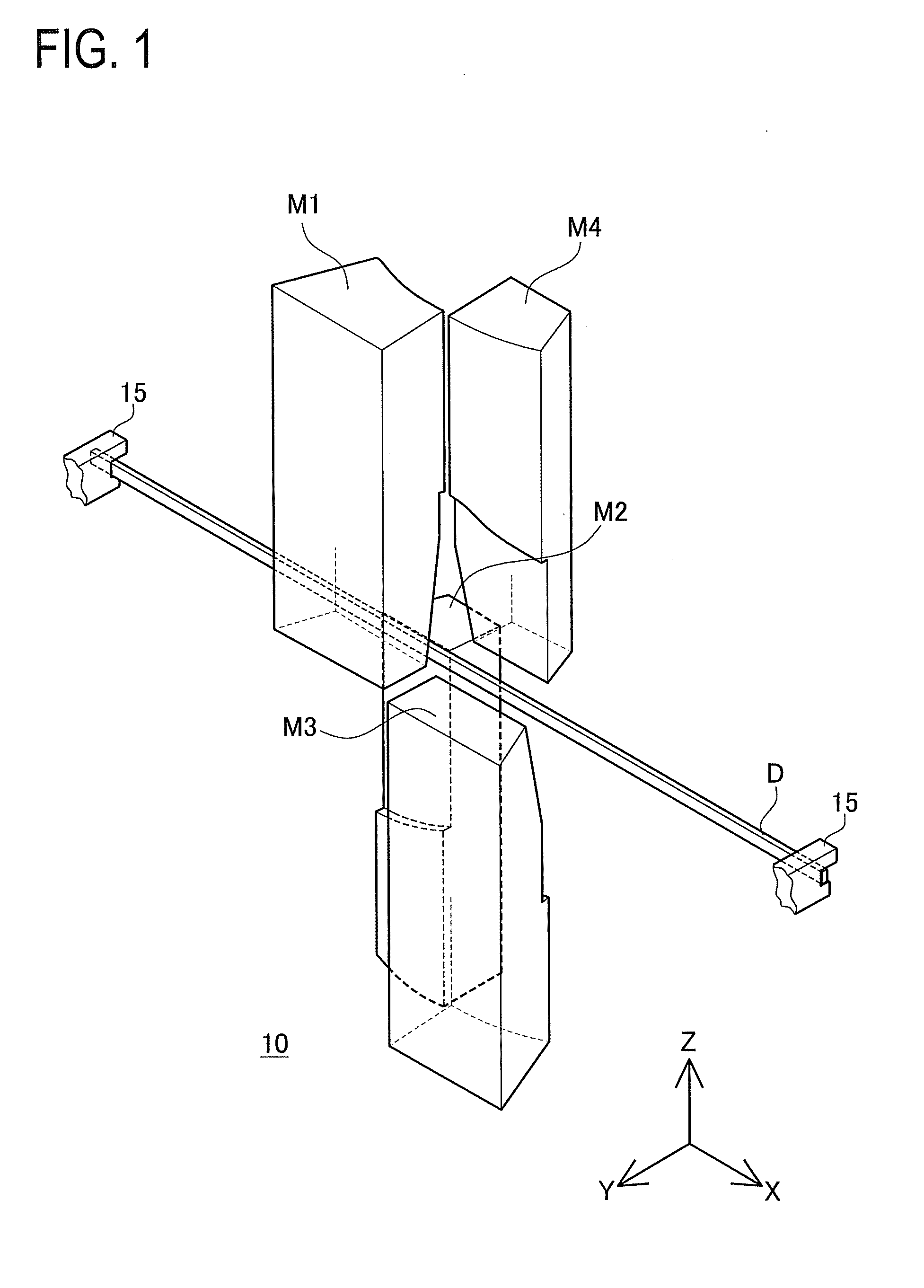
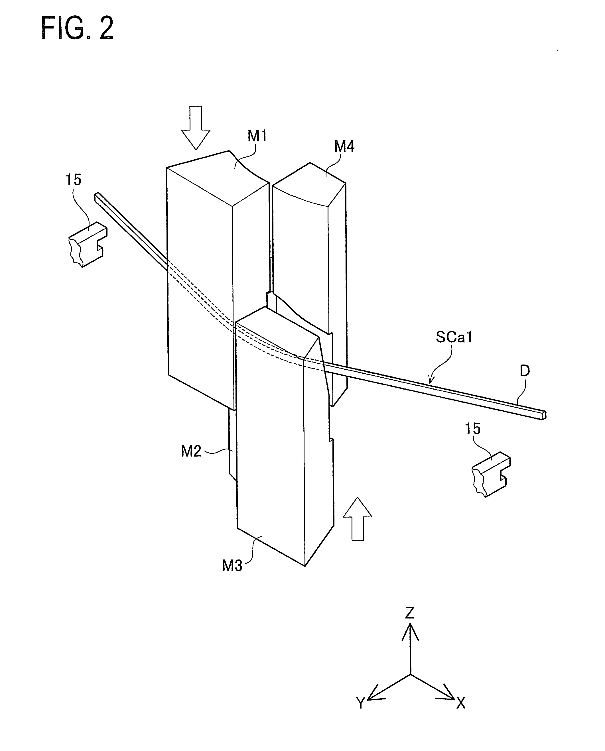
The segment coil manufacturing method described in this patent provides a way to make a segment coil with a circular-arc shaped section, crank-shaped section, and protrusion section without needing to open the dies and change the position of the flat rectangular conductor. This method uses a holding mechanism to hold the conductor in a perpendicular position, which increases processing freedom and shape accuracy. The method also includes forming the circular-arc shaped section and crank-shaped section using forming faces in the first and second forming dies, which allows for continuous plastic deformation of the conductor. Overall, this method reduces cycle time and cost of manufacturing the segment coil.

Problems solved by technology

In particular, a hybrid electric car has to mount an engine and a drive motor together in an engine room and thus highly requires a small-sized motor.
However, when a segment coil is to be made of a flat rectangular conductor, a processing method therefor is somewhat hard.

Method used


Image

  • Segmented-coil manufacturing method, segmented-coil manufacturing device, and segmented coil manufactured using the method and the device
  • Segmented-coil manufacturing method, segmented-coil manufacturing device, and segmented coil manufactured using the method and the device
  • Segmented-coil manufacturing method, segmented-coil manufacturing device, and segmented coil manufactured using the method and the device

Examples


Embodiment Construction

[0093]A detailed description of an embodiment of the present invention will now be given referring to the accompanying drawings.

[0094]FIG. 11 is a perspective view of a segment coil SC in the present embodiment. FIG. 12 is a plan view of the segment coil SC. FIG. 6 is a perspective view of a flat rectangular conductor D. FIG. 7 is a perspective view of the flat rectangular conductor D formed with a circular-arc section. FIG. 8 illustrates the flat rectangular conductor D formed with a crank section. FIG. 9 illustrates the flat rectangular conductor formed with a protrusion section. FIG. 10 illustrates the flat rectangular conductor D formed with shoulder sections. As the segment coil SC, a plurality of segment coils slightly different in shape from one shown in FIG. 11 are required. Since they are similar in shape, however, their details are omitted.

[0095]The segment coil SC is formed of the flat rectangular conductor D shown in FIG. 6. The flat rectangular conductor D is a wire tha...


PUM


Abstract

In a segment coil manufacturing method for manufacturing a segmented coil by bending a flat rectangular conductor using a forming die so that the segmented coil has a circular arc section, a crank section, and a protrusion-shaped section, the forming die includes an outer peripheral surface forming upper die, an inner peripheral surface forming upper die, an inner peripheral surface forming lower die, and an outer peripheral surface forming lower die, and the method includes forming the circular arc section, the crank section, and the protrusion-shaped section while holding at least two surfaces of the outer peripheral surfaces of the flat rectangular conductor by the outer peripheral surface forming upper die, the inner peripheral surface forming upper die, the inner peripheral surface forming lower die, and the outer peripheral surface forming lower die.

Description

TECHNICAL FIELD[0001]The present invention relates to a method for producing a segment coil to be used in a stator of a motor or the like and particularly to a technique for accurately forming the segment coil at low cost.BACKGROUND ART[0002]In recent years, more and more automobiles mount drive motors in view of environmental issues. Such a drive motor to be mounted in a car is desired to provide large output power for driving a vehicle and have a small size for car installation. In particular, a hybrid electric car has to mount an engine and a drive motor together in an engine room and thus highly requires a small-sized motor. To enhance the motor power, there have been methods for increasing a cross sectional area of a coil to be used in the motor and also increasing a space factor or lamination factor of a stator. On the other hand, various approaches for reducing the size of a motor have been studied.[0003]As one of the methods for increasing the cross sectional area of the coi...

Claims


Application Information

Patent Timeline
IPC IPC(8): H01F41/04
CPCH01F41/04H02K15/0421H02K3/12Y10T29/4902
Inventor WATANABE, ATSUSHIKITAMURA, MANABUWATANABE, HAJIMEHASHIMOTO, SHINGOOOTA, TAKANORI
Owner TOYOTA JIDOSHA KK
Learn More