Tip seal having a position indicator, the tip seal being configured to dispense a foam solution

a tip seal and position indicator technology, applied in the field of tip seals, can solve the problems of unfavorable foam out of the tube dripping, and achieve the effect of more economical manufacturing process and simple mold

Active Publication Date: 2014-08-14
ALTACHEM
View PDF9 Cites 12 Cited by
  • Summary
  • Abstract
  • Description
  • Claims
  • Application Information

AI Technical Summary

Benefits of technology

[0014]Since the core part of the tip seal is sealed off from the outside thereof, no obstructions are present inside this core part through which this kind of tip seal is far less sensitive to clogging of the core part thereof.
[0015]Such a kind of tip seal furthermore requires a simpler mould to be manufactured allowing a more economical manufacturing process thereof.
[0016]A further advantage of the tip seal according to the invention is that, because the tube can be sealed off by means of this tip seal, the effect of post-dripping is solved. Post-dripping is the undesired dripping of foam out of the tube because of the presence of remaining pressure and foam in the tube under the influence of the humidity present in de the environmental air.

Problems solved by technology

Post-dripping is the undesired dripping of foam out of the tube because of the presence of remaining pressure and foam in the tube under the influence of the humidity present in de the environmental air.

Method used


Image

  • Tip seal having a position indicator, the tip seal being configured to dispense a foam solution
  • Tip seal having a position indicator, the tip seal being configured to dispense a foam solution
  • Tip seal having a position indicator, the tip seal being configured to dispense a foam solution

Examples


embodiment 7

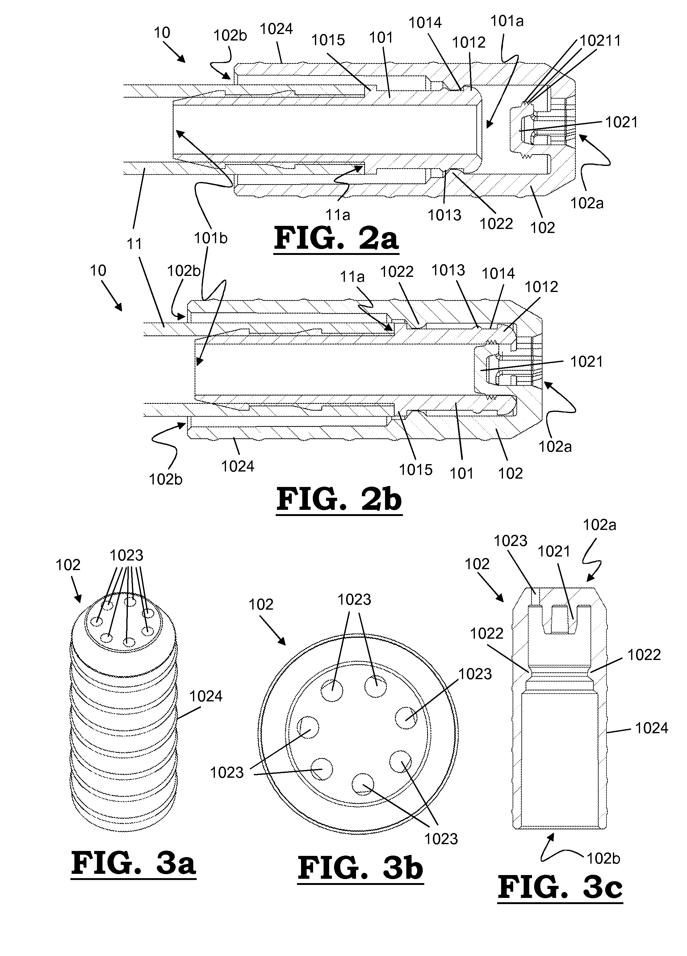
[0072]In FIGS. 3a-3c, a plurality, in this embodiment 7, round orifices are arranged along the outer circumference of the proximal end (102a) of the cap part (102) and around the sealing cap (1021).

embodiment 3

[0073]In FIGS. 4a-4c, a plurality, in this embodiment 3, triangle-like shaped orifices (1023) extending directly around the sealing cap (1021) are provided.

embodiment 4

[0074]In FIGS. 5a-5c, a plurality, in this embodiment 4, square-like shaped orifices (1023) extending directly around the sealing cap (1021) are provided.

[0075]In FIGS. 6a-6c, a plurality, in this embodiment 3, oblong orifices (1023) are arranged along the outer circumference of the proximal end (102a) of the cap part (102) and around the sealing cap (1021).

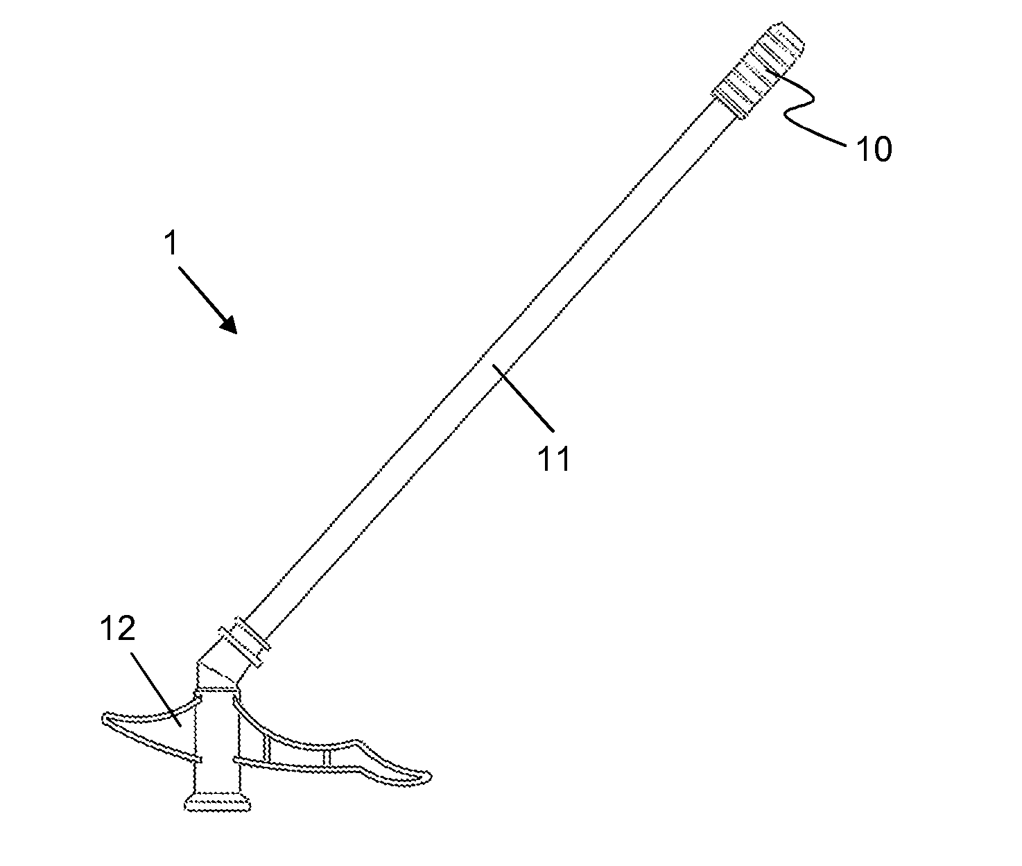
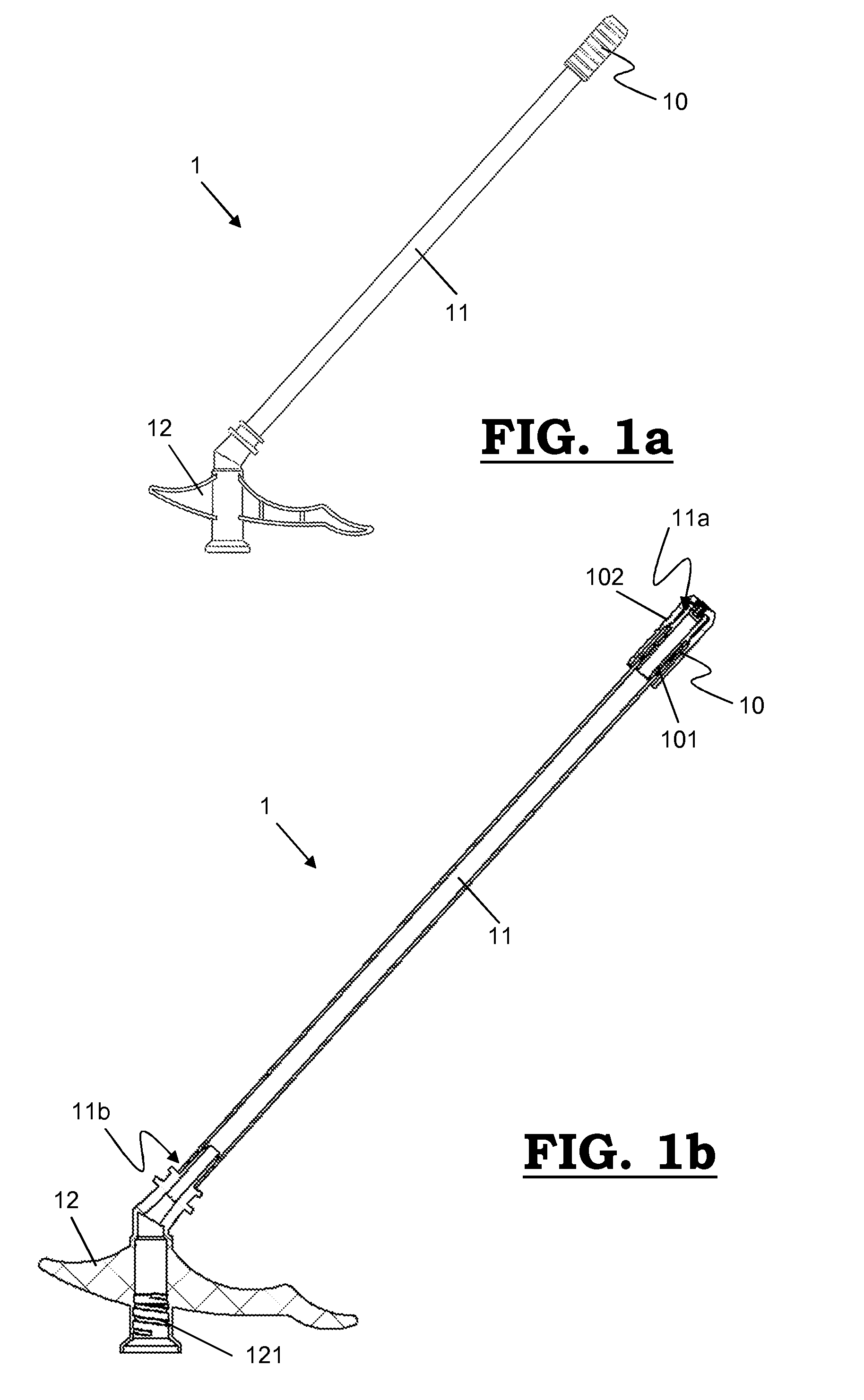
[0076]In FIGS. 7a-7d, a further embodiment similar to that of FIGS. 4a-4c is shown comprising a position indicator. This means in general a tip seal 10 adapted to dispense a foam when connected to a distal end 11b of a tube 11 of an adapter 1 that is configured to be connected to a pressurized dispensing container comprising a viscous foamable solution that is converted into said foam when leaving said container. As explained above, said adapter 1 comprises said tube 11 which at its distal end 11b is in connection with said container and at its proximal end 11a is connected with said tip seal 10, and which is adapted to convey sa...


PUM


Abstract

The invention relates to a tip seal (10) for an adapter (1) and such an adapter (1) for a pressurized dispensing container comprising a viscous foamable solution, said adapter (1) comprising a tube (11) in connection with said container and conveying the into foam converted viscous foamable solution towards said tip seal (10), said tip seal (10) comprising a core part (101) with an at least partially open proximal end (101a) and at least partially open distal end (101b), said core part (101) at least partially being inserted into said tube (11) at said proximal end (101a); and a cap part (102) which is movably connected with said core part (101) at said distal end (102b) of said core part (101) between an open position and a closed position of said tip seal (10), wherein said cap part (102) comprises a closure element (1021) which is adapted for closing off said at least partially open distal end (101b) of said core part (101) in said closed position of said tip seal (10).

Description

FIELD OF THE INVENTION [0001]The present invention relates to a tip seal for an adapter that is configured to be connected to a pressurized dispensing container comprising a viscous foamable solution that is converted into foam when leaving said container, such as polyurethane (PUR) foams. In particular, it concerns such a tip seal that is adapted to dispense said foam and comprises a core part comprising an at least partially open proximal end and at least partially open distal end, wherein said distal end of said core part is adapted to be inserted into said tube, and comprises a cap part which is movably connected with said core part at said distal end of said core part between an open position of said tip seal wherein said foam is dispensable and a closed position of said tip seal wherein said foam is non-dispensable, said cap part comprising at least one dispensing orifice to dispense said foam.[0002]The present invention furthermore also relates to an adapter that is configure...

Claims


Application Information

Patent Timeline
Patent Type & Authority Applications(United States)
IPC IPC(8): B65D47/12
CPCB65D47/12B05B11/0032B65D83/202B65D83/303B65D83/345B65D83/753B65D83/56B05B1/3073B67D7/06B65D51/00
Inventor DEMEY, JORDIOESER, FELIXPITTL, OSKAR
Owner ALTACHEM
Why Eureka
Try Eureka