

Fuel injector valve
- Summary
- Abstract
- Description
- Claims
- Application Information
AI Technical Summary
Benefits of technology
Problems solved by technology
Method used
Image

Examples
Embodiment Construction
[0030]Preferred exemplifying embodiments of a fuel injection valve 1 will be described in detail below with reference to FIGS. 1 to 7. Identical or functionally identical components are labeled in the exemplifying embodiments with the same reference characters.
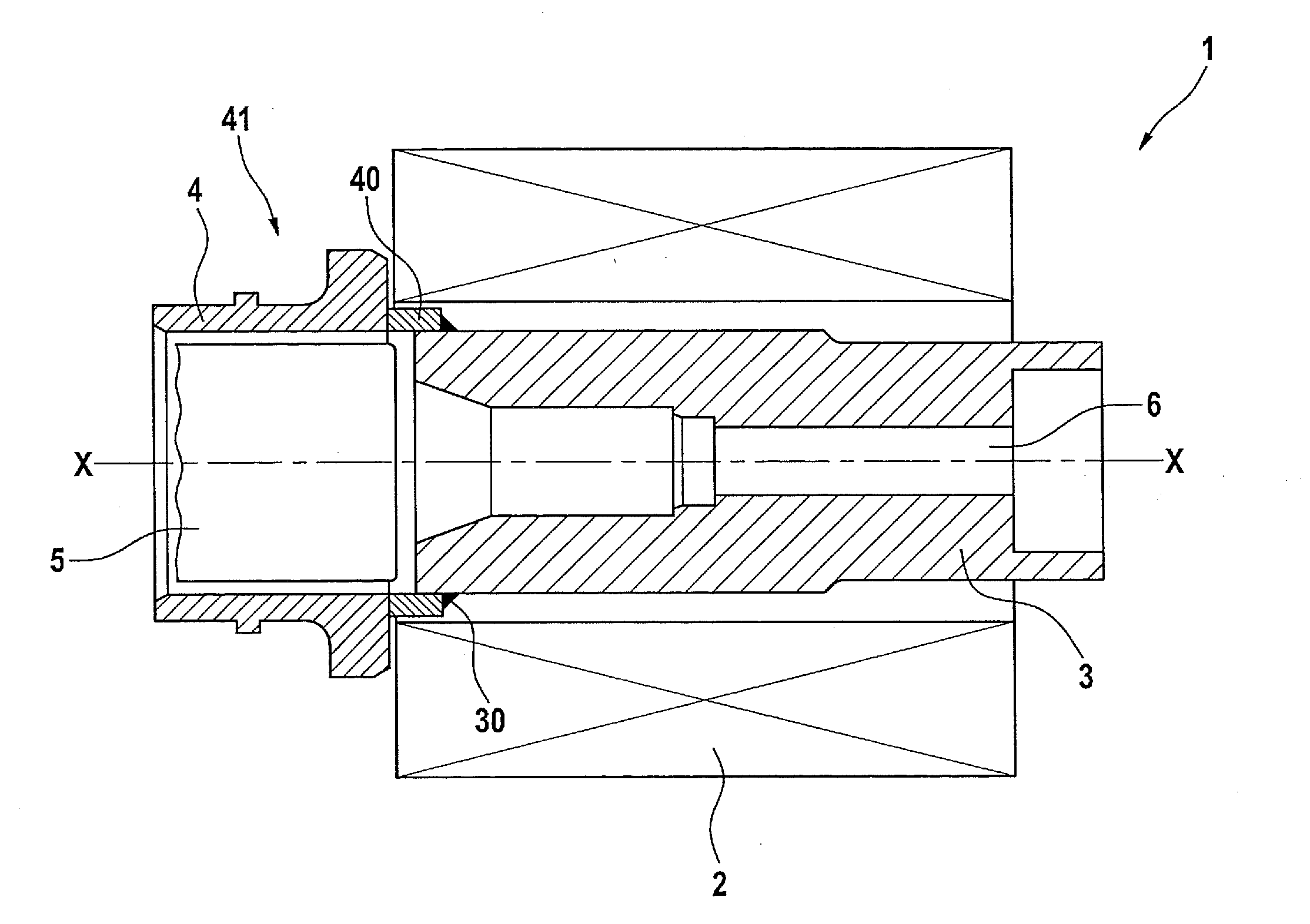
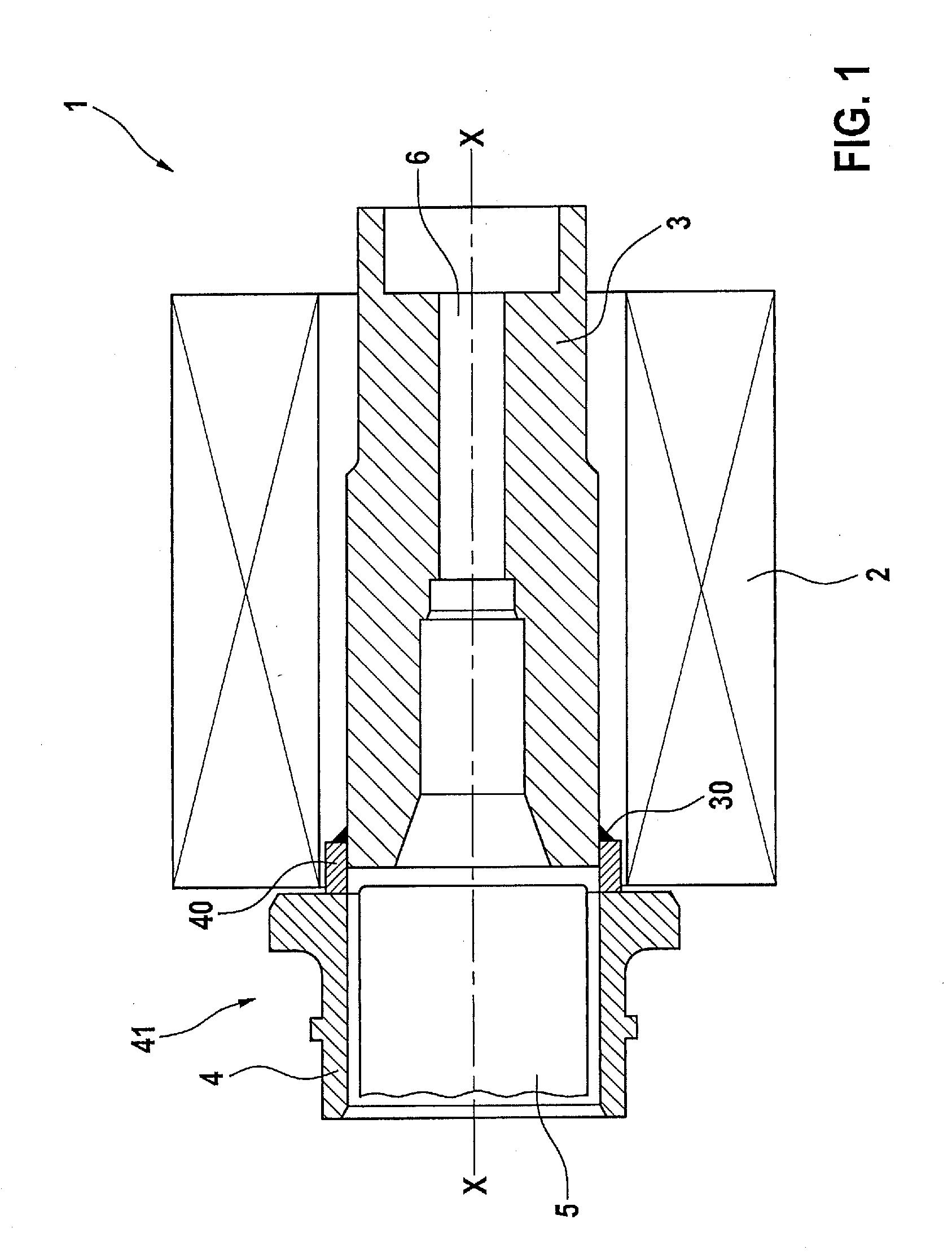
[0031]FIG. 1 and FIG. 2 are sectioned views of a subregion of a fuel injection valve 1 in accordance with a first exemplifying embodiment of the invention, which encompasses a coil 2, an internal pole 3, a valve sleeve 4, a magnetic separating element 40, and a magnet armature 5. Magnetic separating element 40 is embodied here in annular cylindrical fashion, and is attached to internal pole 3 by way of a welded join 30. Instead of welded join 30, a soldered join can alternatively also be provided. Internal pole 3 has a centered passthrough opening 6 extending in an axial direction X-X.
[0032]As illustrated by the sectioned depiction of FIG. 2, valve sleeve 4 and magnetic separating element 40 of the first exemplifying embodimen...
PUM
| Property | Measurement | Unit |
|---|---|---|
| Fraction | aaaaa | aaaaa |
| Fraction | aaaaa | aaaaa |
| Thickness | aaaaa | aaaaa |
Abstract
Description
Claims
Application Information