System for in-flight restarting of a multi-shaft turboprop engine

Inactive Publication Date: 2014-08-14
ALENIA AERMACCHI
View PDF0 Cites 9 Cited by
  • Summary
  • Abstract
  • Description
  • Claims
  • Application Information

AI Technical Summary

Benefits of technology

[0009]The foregoing object is achieved by the present invention in so far as it relates to a multi-shaft aeronautical turboprop engine comprising a casing housing a compressor that draws in air coming from an air intake and drives, through a first shaft, a first stage of a turbine set in rotation by exhaust gases coming from a plurality of burners; the turbine being provided with a second stage that drives a propeller by means of a second shaft; said turboprop engine being characterized in that it comprises a starting system comprising: an asynchronous reversible electric machine connected by means of a transmission to the first shaft; a synchronous electric machine connected by means of a transmission to the second shaft; a reconfigurable electrical network that, in a phase of dynamic starting of the turboprop engine following its cutting out during flight, enables the transfer of energy produced by the synchronous electric machine, working as a generator under the thrust of the propeller driven by dynamic effects, to the asynchronous electric machine, which operates as motor and turns at a lower speed than

Problems solved by technology

Starting operations of the turboprop engine are easy on the runway, but can become extremely critical in flight, as the energy available on board can be limited in many operating conditions.
In addition, in such conditions, the rotational energy deriving from propeller being driven by the forward movement of the aircraft (known as

Method used


Image

  • System for in-flight restarting of a multi-shaft turboprop engine
  • System for in-flight restarting of a multi-shaft turboprop engine
  • System for in-flight restarting of a multi-shaft turboprop engine

Examples


Example

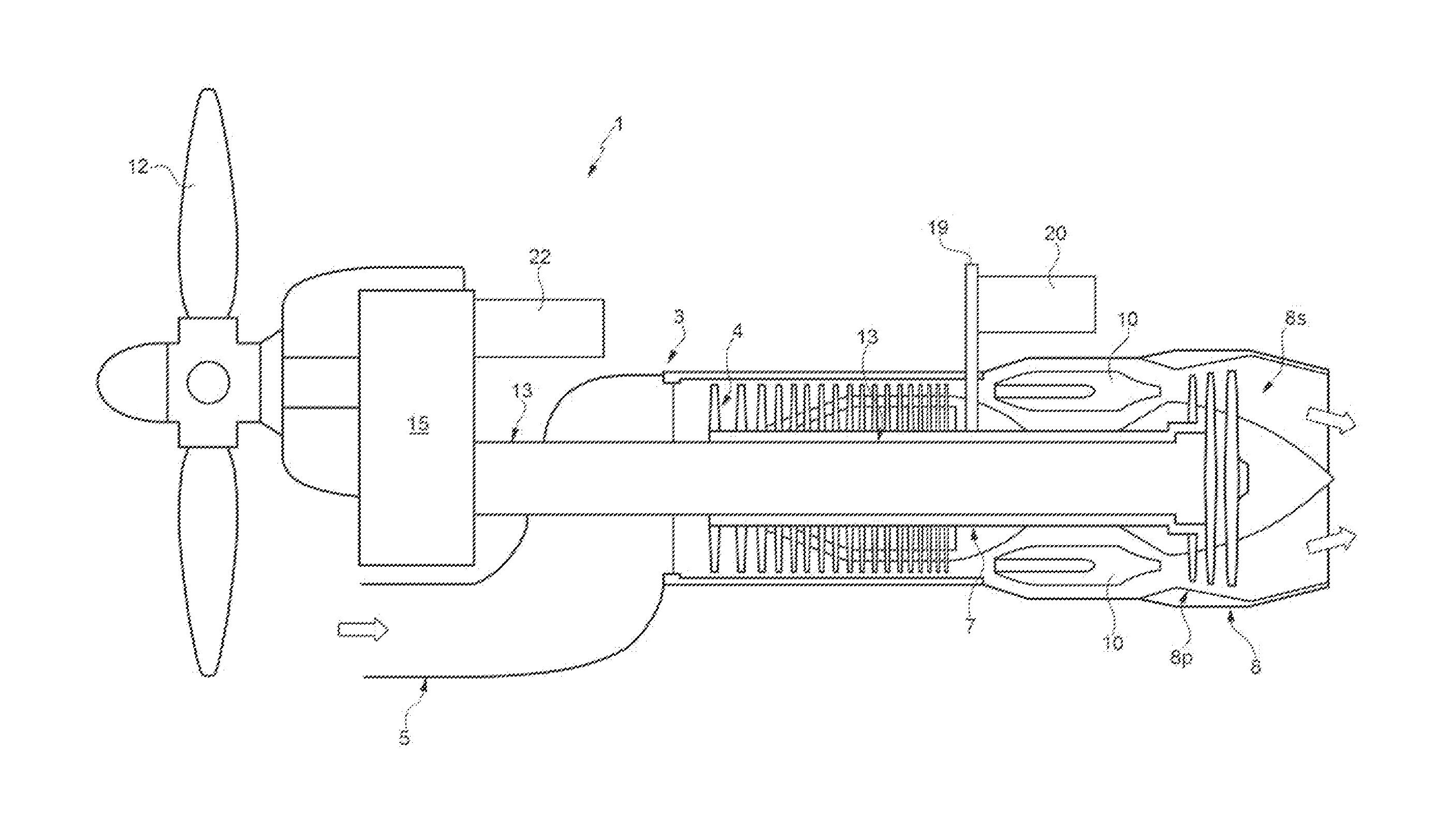
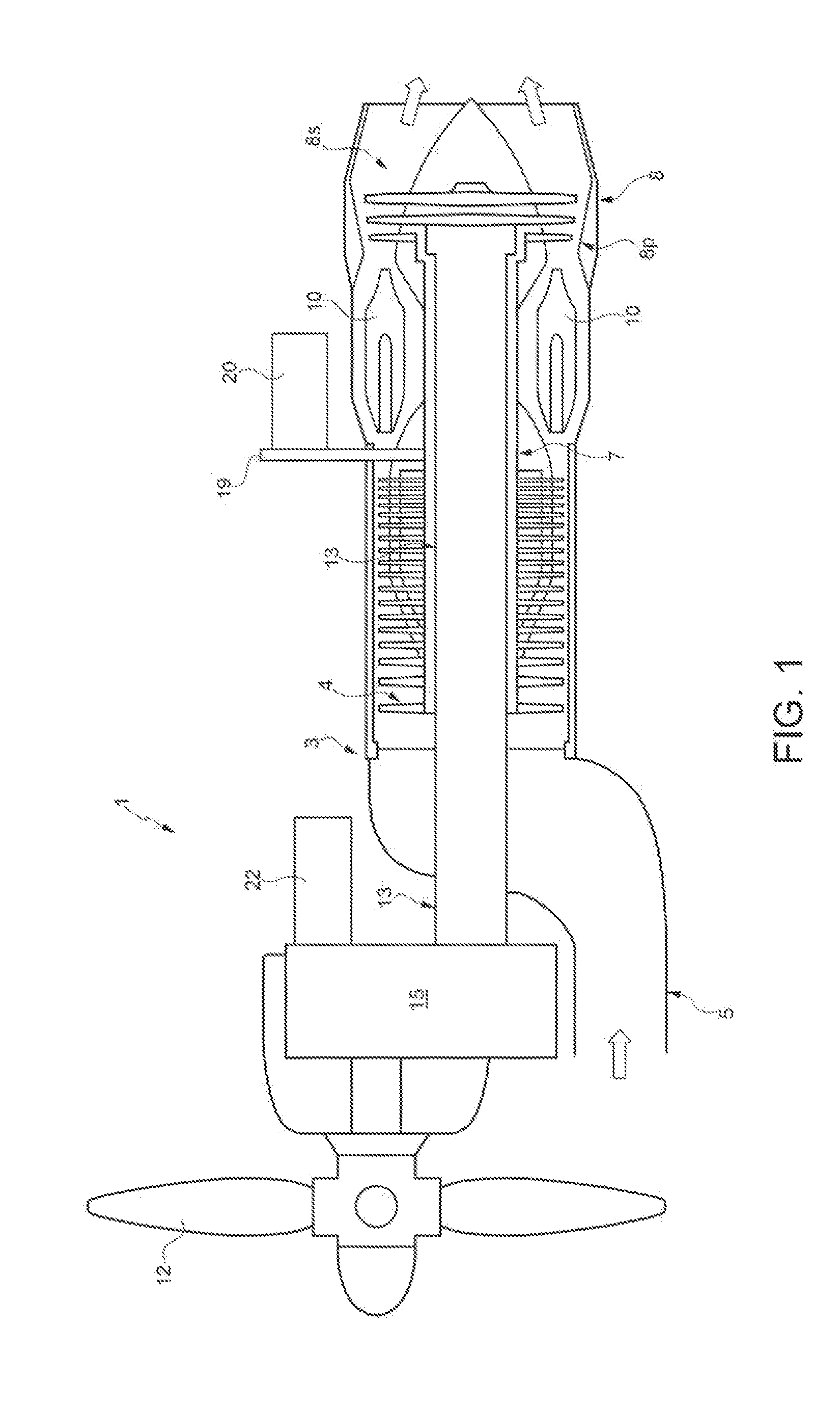
[0015]FIG. 1 shows a multi-shaft aeronautical turboprop engine, indicated as a whole by reference numeral 1, equipped with a starting system made according to the present invention.

[0016]The structure of the multi-shaft turboprop engine 1 is of known type and will therefore only be described and illustrated schematically. In particular, the turboprop engine 1 comprises an elongated tubular casing 3, which houses a blade compressor 4 that draws in air coming from an air intake 5 connected to a front portion of the elongated tubular casing 3 and drives, through an outer first shaft 7, a first stage 8p of a turbine 8, which is set in rotation by exhaust gases coming from a plurality of burners 10.

[0017]The turbine 8 is provided with a second stage 8s that drives the propeller 12 by means of a second shaft 13 mounted coaxially inside the first shaft 7. In particular, a first rear end of the inner second shaft 13 carries the blades of the second stage 8s, while a first front end of the i...


PUM


Abstract

A multi-shaft aeronautical turboprop engine in which a compressor draws in air coming from an air intake and drives, through an outer first shaft, a first stage of a turbine, which is provided with a second stage that drives a propeller by means of a second shaft mounted coaxially inside the first shaft. A starting system. is provided that comprises: an asynchronous reversible electric machine connected by means of a transmission to the first shaft; a synchronous electric machine connected by means of a transmission to the second shaft; a reconfigurable electrical network that, in a phase of dynamic starting of the turboprop engine following its cutting out during flight, enables the transfer of energy produced by the synchronous electric machine, set in rotation by the propeller driven by dynamic effects, to the asynchronous electric machine, which is set in rotation at a lower speed than the asynchronous machine. The torque generated by the asynchronous machine is added to the torque originating from the blade compressor, which is impinged upon by the airflow coming from the air intake; the composition of these torques enables the first shaft to be set in rotation at a speed sufficient to achieve the restarting of the turboprop engine.

Description

TECHNICAL FIELD[0001]The present invention relates to a system for the in-flight restarting of a multi-shaft aeronautical turboprop engine.BACKGROUND OF THE INVENTION[0002]Multi-shaft turboprop engines for aeronautical use are provided with a compressor that draws in air coming from an air intake and drives, through a first shaft, a first stage of a turbine that is set in rotation by exhaust gases coming from a plurality of burners. The turbine is provided with a second stage that drives the propeller by means of a second shaft, which is usually mounted coaxially inside the first shaft.[0003]The starting of these multi-shaft turboprop engines is performed by means of an electric starter, in which an electric motor is connected to the first shaft to set the compressor and the first stage of the turbine in rotation. Patent U.S. Pat. No. 4,799,354 illustrates an example of the above-mentioned type of starting system.[0004]The energy necessary for this starting operation is taken from a...

Claims


Application Information

Patent Timeline
IPC IPC(8): F02N11/00
CPCF02N11/006F01D15/10F02N11/04F02C6/206F02C7/262F02C7/268H02P9/08F02N11/0866F02N2011/0888F02N2011/0896H02P2101/30
Inventor ANASTASIO, VINCENZOCUOMO, FABRIZIO
Owner ALENIA AERMACCHI
Why Eureka
Try Eureka