
Motor-driven travelling body and high-speed charge method for motor-driven travelling body

a technology of motor-driven travelling body and high-speed charging, which is applied in the direction of secondary cell servicing/maintenance, battery/fuel cell control arrangement, electric devices, etc., can solve the problem of taking a relatively long time to charge, and achieve the effect of enhancing mobility, facilitating charging work, and high performan

Inactive Publication Date: 2014-08-14
INST FOR ENERGY APPL TECH
View PDF1 Cites 23 Cited by
  • Summary
  • Abstract
  • Description
  • Claims
  • Application Information

AI Technical Summary

Benefits of technology

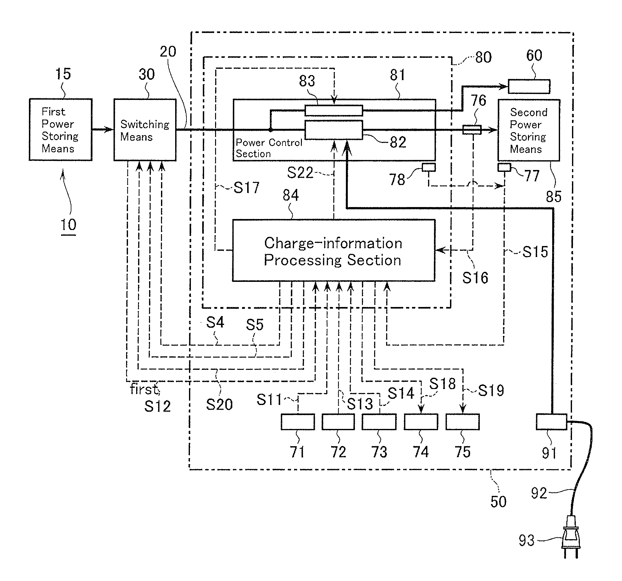
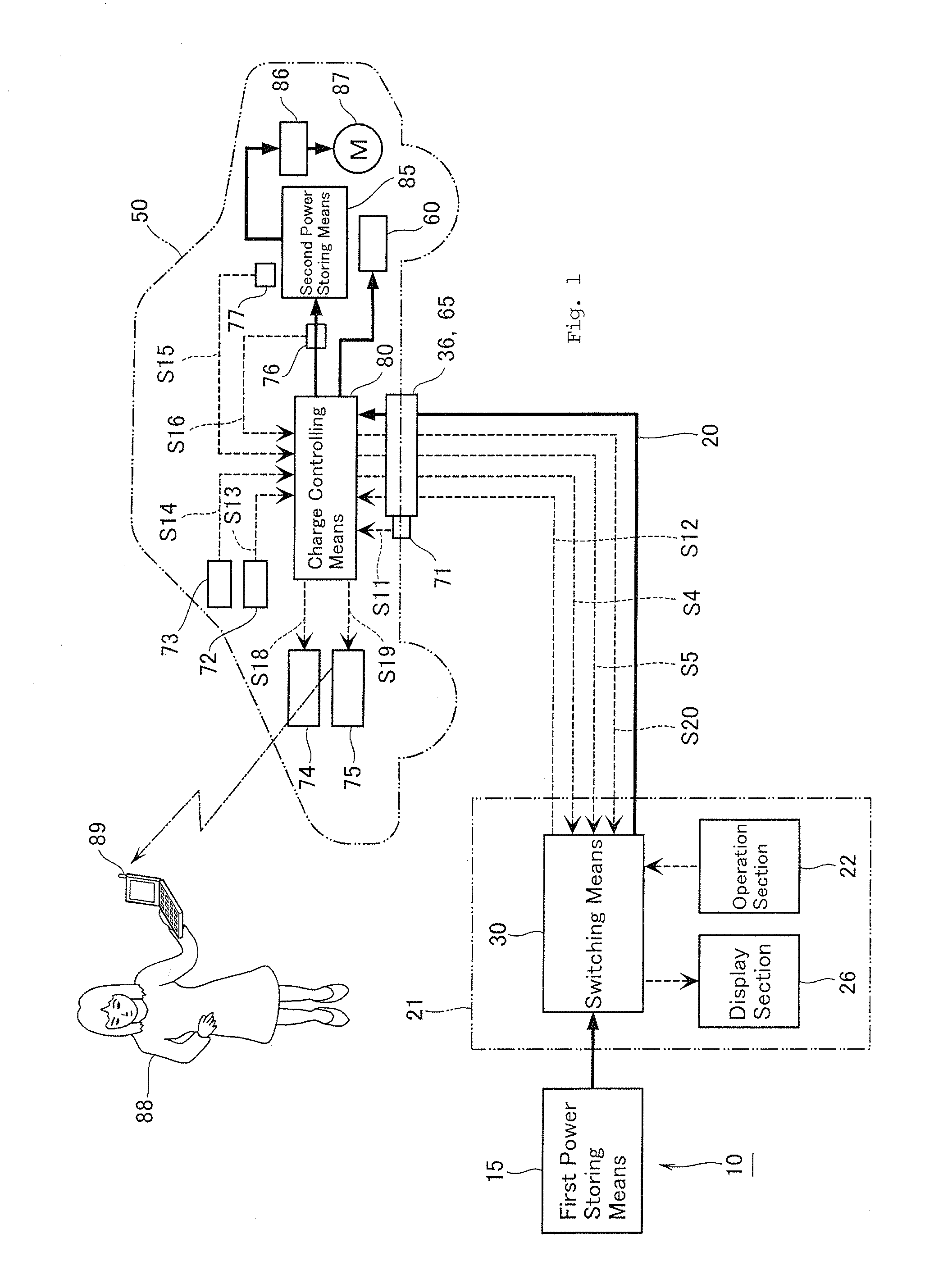
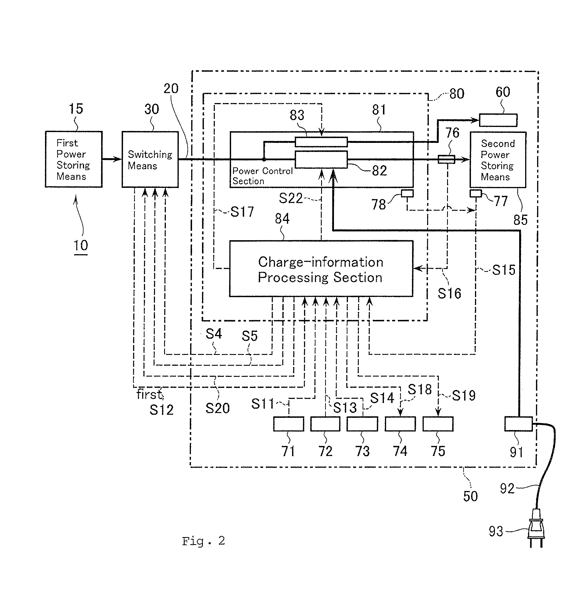
[0018]The electrically-driven mobile body according to claim 1 and the boosting charge method for an electrically-driven mobile body according to claim 7 are capable of controlling electric power supplied by the power supply apparatus in such a way that the electric power has a voltage and an electric current suitable forgiving the power storing means a boosting charge. This make it possible to give an electrically-driven mobile body having different charging conditions a boosting charge with electric power supplied by the same power supply apparatus. The charge control is extremely significant because it may affect the life or the like of the power storing means. In designing an electrically-driven mobile body having a charge control function fitted for the power storing means, the charge control can be determined by fully studying characteristics of the power storing means. Conventionally, a boosting-charge apparatus and an electrically-driven mobile body such as a vehicle are each produced by a separate manufacturer, but an electrically-driven mobile body is provided with a charge control function, thereby enabling the mobile-body manufacturer to design the power storing means and the charge control together. This makes it possible to design the power storing means in such a way that it has a higher performance, thereby enhancing the mobility (e.g., potential traveling distance) of the electrically-driven mobile body. Besides, the cooling means cools a heat-generation part of the charging system with electric power supplied by the power supply apparatus, thereby saving supplying a coolant from the outside, so that the charging work becomes easier and the apparatus configuration simpler.
[0019]According to claim 2, the electronic cooling element operating with electric power from the power supply apparatus cools a heat-generation part of the charging system, thereby saving a coolant such as chlorofluoro carbon and hence contributing toward improving the global environment.
[0020]According to claim 3, the charge controlling means includes a charge control unit having a DC chopper circuit, and thereby, even if the charging voltage for the power storing means differs from the output voltage of electric power supplied by the power supply apparatus, it can be regulated to an optimum voltage for giving a boosting charge to the power storing means.
[0021]According to claims 4 and 5, the power storing means has a higher energy density and stores a greater amount of electric power, thereby lengthening the traveling distance of the electrically-driven mobile body for one boosting charge.
[0022]According to claim 6, the charge-completion alarming means notifies a portable receiver of the driver that the power storing means has been charged, thereby permitting the driver to stay away from the electrically-driven mobile body while being charged and spend the charging time effectively.
[0023]According to claim 8, the electrically-driven mobile body can be supplied with high-quality electric power equivalent to pure DC power, thereby almost saving considering a noise, a surge or the like in designing electric circuits of the electrically-driven mobile body, so that the electric circuits of the electrically-driven mobile body can be more easily designed.
[0024]According to claim 9, the electrically-driven mobile body is supplied with electric power from the power supply apparatus with the conductors thereof being in contact in a conductive charging method as well as with the conductors being out of contact using electro-magnetic induction in an inductive charging method, thereby facilitating the charging work.
[0025]According to claim 10, the electrically-driven mobile body is supplied with electric power generated using renewable energy, thereby generating electric power without emitting carbon dioxide and hence contributing toward improving the global environment.

Problems solved by technology

An electric vehicle, emitting no exhaust gas and environment-friendly, has the problem of taking a relatively long time to charge.

Method used


Image

  • Motor-driven travelling body and high-speed charge method for motor-driven travelling body
  • Motor-driven travelling body and high-speed charge method for motor-driven travelling body
  • Motor-driven travelling body and high-speed charge method for motor-driven travelling body

Examples


first embodiment

[0041]FIGS. 1 to 9 show a first embodiment of the present invention. In FIG. 5, reference numeral 1 denotes a commercial AC power source such as a three-phase AC power source which supplies electric power through a power line 2 into a construction 3. The construction 3 houses: a rectifier 11 as a power supplying means constituting a power supply apparatus 10; a power-supply controlling means 12; a first power storing means 15; and other equipment. The rectifier 11 is connected on the input side to the power line 2 inside of the construction 3 and-has the function of converting three-phase AC power from the power line 2 into DC power after regulating it to a predetermined voltage. On the output side, the rectifier 11 is connected via the power-supply controlling means 12 to the first power storing means 15. As described later, the power-supply controlling means 12 has the function of stopping the rectifier 11 from supplying DC power to the first power storing means 15 based on a sign...

second embodiment

[0067]FIG. 10 shows a second embodiment of the present invention which is applied to a boosting charge for a ship as an electrically-driven mobile body. As shown in FIG. 10, a second power storing means 85d of a passenger ship 100, a second power storing means 85e of a motorboat 101, a second power storing means 85f of a car ferry 102 and a second power storing means 85g of a bathyscaphe 103 can be supplied with electric power for charge through each charging circuit 20 connected in parallel to the first power storing means 15. In view of improvements in the global environment, more ships propelled by electric power should desirably be used. As a prime mover for shipping, for example, a high-temperature super conducting motor having a high performance may desirably be employed. In this implementation, the pure DC power supplied from the first power storing means 15 is controlled to charge each ship, and thereby, the charging voltage and charging current for each second power storing...

third embodiment

[0068]FIG. 11 shows a third embodiment of the present invention which is applied to a boosting charge for an aircraft as an electrically-driven mobile body. As shown in FIG. 11, a second power storing means 85h of a twin-engine aircraft (including a vertical take-off and landing (VTOL) aircraft) 110, a second power storing means 85i of a single-engine aircraft 111, a second power storing means 85j of a helicopter 112 and a second power storing means 85k of an airship 113 can be supplied with electric power for charge through each charging circuit 20 connected in parallel to the first power storing means 15. In view of improvements in the global environment, more aircraft propelled by electric power should desirably be used. It is desirable that an aircraft has a prime mover such as a light core-less motor. Each aircraft makes a flight by rotating a propeller or a rotor blade with electric power from the first power storing means 15. In this implementation, the pure DC power supplied...


PUM


Abstract

An electrically-driven mobile body which can be given a boosting charge with electric power supplied by a single power supply apparatus together with other electrically-driven mobile bodies having different charging conditions and which can cool a charging system thereof without any coolant from the outside, as well as a boosting charge method for an electrically-driven mobile body for the same purpose.An electrically-driven mobile body (50) which includes a power storing means (85) storing DC power supplied by an external power supply apparatus (10) and is driven with DC power stored in the power storing means (85), includes: a charge controlling means (80) for controlling DC power supplied by the power supply apparatus (10) in such a way that the DC power has a voltage and an electric current suitable for giving the power storing means (85) a boosting charge; and a cooling means (60) for cooling a charging system of the power storing means (85) forcedly with DC power supplied by the power supply apparatus (10).

Description

TECHNICAL FIELD [0001]The present invention relates to an electrically-driven mobile body such as a vehicle and a ship having an electric motor as the prime mover thereof, and particularly, it relates to an electrically-driven mobile body given a boosting charge with electric power supplied by an external power supply apparatus and a boosting charge method for an electrically-driven mobile body for the same purpose.[0002]An electric vehicle, emitting no exhaust gas and environment-friendly, has the problem of taking a relatively long time to charge. In order to shorten the charge time, the electric vehicle has to be given a great amount of electric power in a short time, thereby requiring power equipment having a larger power capacity in a location where only a low-voltage power line is laid. Hence, an electric vehicle is generally given a boosting charge by rectifying commercial AC power, storing DC power in a storage battery and utilizing the stored DC power (refer to Patent Docum...

Claims


Application Information

Patent Timeline
Patent Type & Authority Applications(United States)
IPC IPC(8): B60L11/18
CPCB60L11/1809B60L11/1816B60L11/182B60K2001/0438B60L1/003B60L3/0046B60L3/04B60L2240/36H01G9/28H01M10/0525H01M10/44H01M10/46H01M10/465H01M10/486Y02T90/14Y04S30/14B60L53/14B60L53/12B60L53/31B60L53/64B60L53/11B60L58/26B60L50/66B60L53/305B60L53/51B60L53/52B60L53/53B60L58/10Y02E60/10Y02T10/70Y02T10/7072Y02T90/12Y02T90/167Y02T90/16B60L53/00
Inventor SUGANO, TOMIO
Owner INST FOR ENERGY APPL TECH
Learn More