
Shock absorbing implantable limb prosthetic

a technology of implantable limbs and prosthetics, applied in the field of shock absorption implantable limb prosthetics, can solve the problems of specific disadvantages of lower limb amputees, affecting the stability of standing or ambulation, so as to reduce pain and discomfort, improve the dynamic interaction, and high

Active Publication Date: 2014-08-14
SMITH LARRY N
View PDF3 Cites 0 Cited by
  • Summary
  • Abstract
  • Description
  • Claims
  • Application Information

AI Technical Summary

Benefits of technology

The invention solves the problem of excessive force on the amputated limb by providing an implantable device that can distribute the weight and force of walking over a larger surface area, reducing pain and discomfort. The device includes a resilient-support, such as an elastomeric solid or gel, that acts similar to a natural joint and protects the surrounding residual tissues from the forces of ambulation. The device can be modular, allowing for certain components to be removed, replaced, or upgraded, if necessary, without removal of the entire device. Overall, the invention provides a more convenient and comfortable alternative implanted prosthetic device that reduces overall stress on the residual limb, the entire body.

Problems solved by technology

Lower-limb amputees are at a specific disadvantage because their musculo-skeletal system has been compromised by the loss of some these shock-absorbing hydrodynamic structures.
For amputees, the forces associated with standing or ambulation become problematic because they can no longer be adequately absorbed and dissipated throughout their entire musculo-skeletal system.
But, even with high-quality residual tissue over and surrounding the terminal bone end, the forces of ambulation can be only partially distributed, making ambulation difficult and often painful for amputees, even under the best circumstances.

Method used


Image

  • Shock absorbing implantable limb prosthetic
  • Shock absorbing implantable limb prosthetic
  • Shock absorbing implantable limb prosthetic

Examples


Embodiment Construction

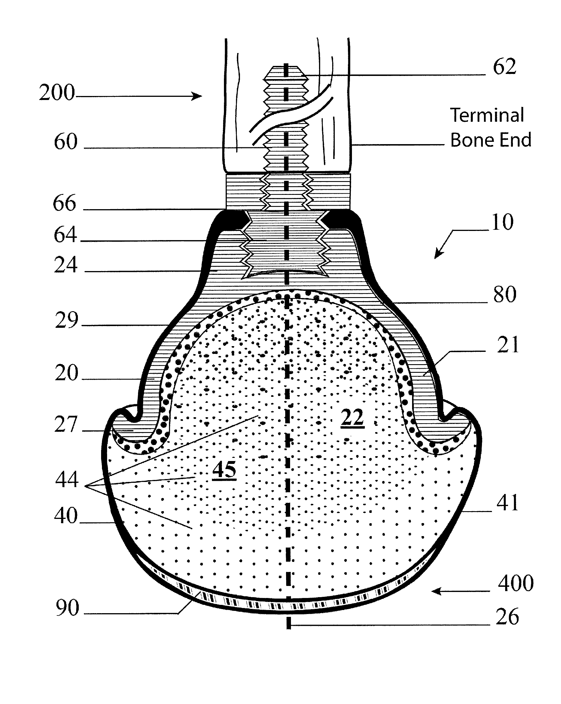
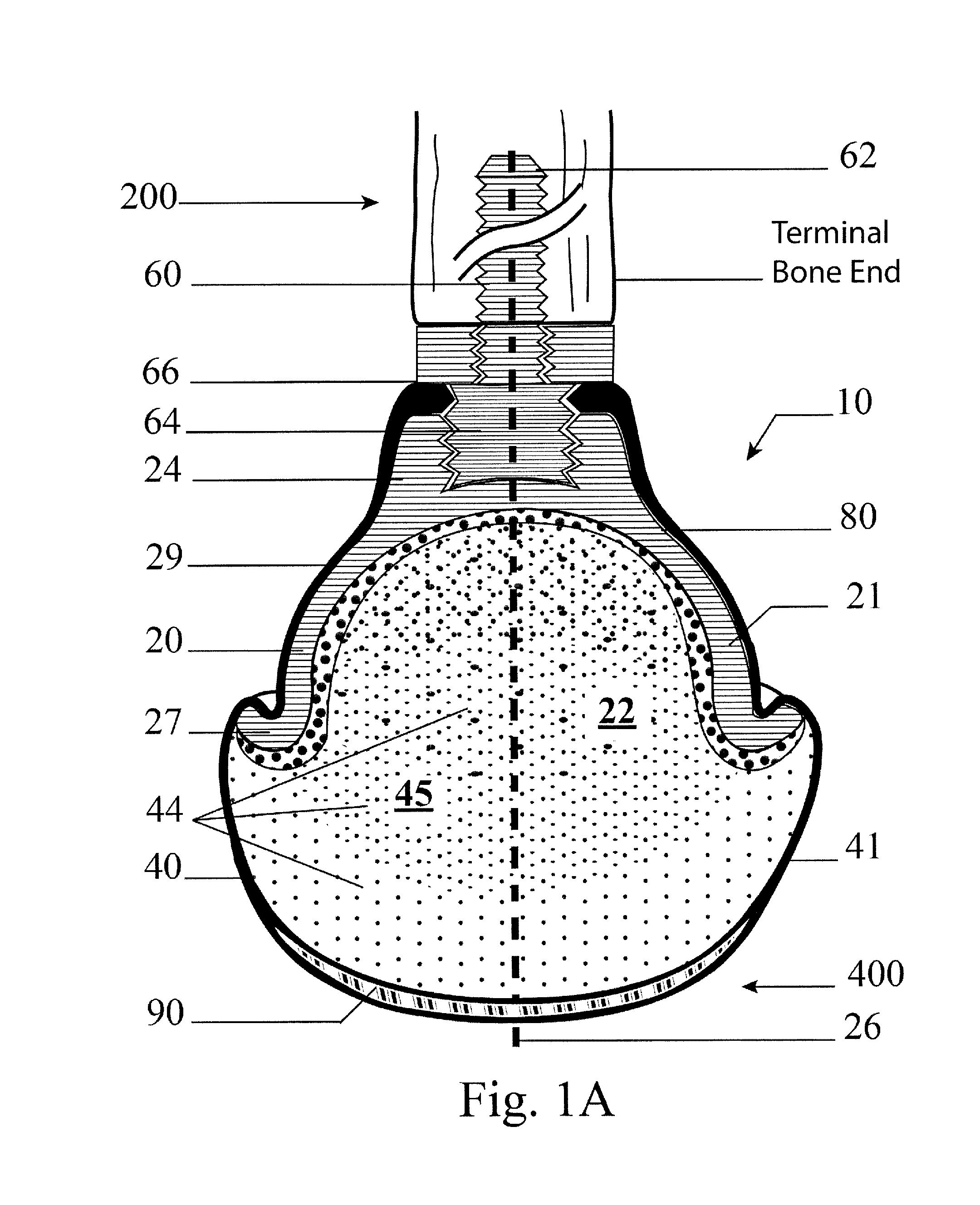
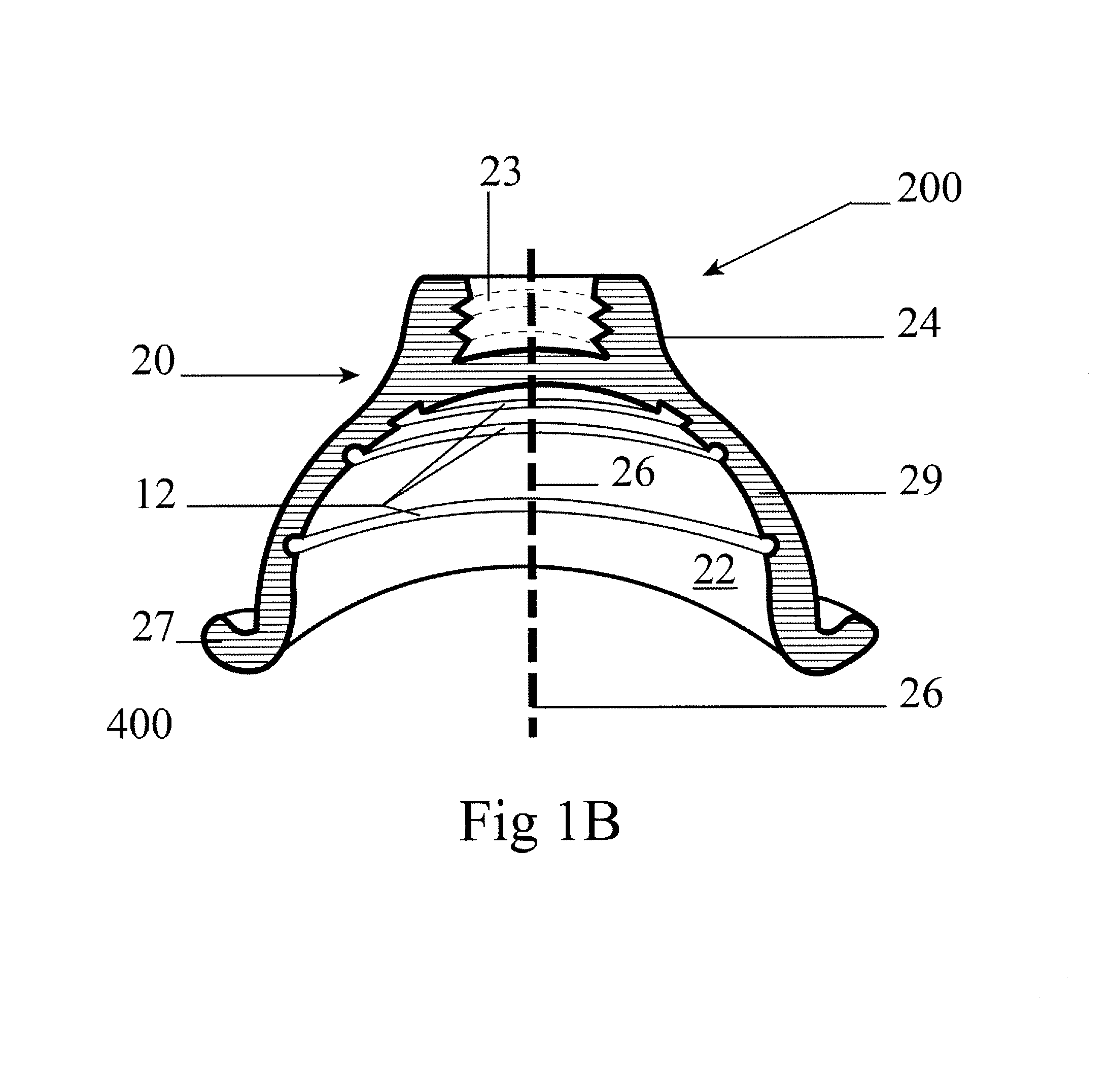
[0033]The subject invention describes embodiments of a device for implantation into the residual end of an amputated limb. More specifically, the subject invention provides one or more embodiments of an implantable force-distribution support structure (FDSS) that can be fixed to the terminal bone end or bone stump in a residual limb. The FDSS can operate similarly to the natural hydrodynamic system of the skeleton, replacing, at least partially, what was lost with an amputation.

[0034]The following description will disclose that the embodiments of the subject invention are particularly useful for lower extremity amputations, in particular when used with external devices to provide ambulation to an amputee. However, a person with skill in the art will be able to recognize numerous other uses, such as, for example, upper body amputations, that would be applicable to the devices and methods of the subject invention. Thus, while the subject application describes embodiments for specific ...


PUM


Abstract

The subject invention pertains to embodiments of a device for implantation into a residual amputated limb. More specifically, the subject invention provides one or more embodiments of an implantable force-distribution support that can be installed onto the terminal end of a bone or bone stump in a residual limb. The force-distribution support can restore the natural hydrodynamic system of the skeleton and can re-engage the axial skeleton as a factor in absorbing forces of ambulation. Embodiments can include a support bracket that can be attached to the terminal bone end to which a resilient-support can be attached to protect residual tissue from compression forces.

Description

BACKGROUND OF INVENTION[0001]Limb amputations have been a part of human existence since the earliest beginnings. While the reasons for such traumas vary and have changed over the centuries, limb amputations continue to account for a significant portion of major injuries each year. Currently, over 1.6 million people currently live with the loss of a limb and that number is expected to double by 2050. Over 30% of those people have lost a lower extremity. The difficulties of living and working with a prosthetic limb remain almost the same as they have from the earliest days. Various types of prosthetic limbs have been devised over time to assist individuals with lower limb amputations. Today's prosthetic limbs are highly sophisticated with a vast array of light-weight materials and ergonomic designs to facilitate normal walking patterns.[0002]Notwithstanding all of the improvements to external prosthetic limbs, a lower-extremity amputee still faces the difficulty of being able to adjus...

Claims


Application Information

Patent Timeline
Patent Type & Authority Applications(United States)
IPC IPC(8): A61B17/86
CPCA61B17/8605A61F2/2814A61F2002/30069A61F2002/30301A61F2002/30405A61F2002/30507A61F2002/3085
Inventor SMITH, LARRY N.
Owner SMITH LARRY N
Learn More