
Gas delivery system for outputting fast square waves of process gas during semiconductor processing

a gas delivery system and semiconductor technology, applied in the field of semiconductor processing, can solve the problems of large gas flow that quickly decays, creates a bottleneck in semiconductor processing, and often is not seen. actual flow profiles are often unknown, and the actual flow profile is not seen

Active Publication Date: 2014-08-21
ICHOR SYST INC
View PDF8 Cites 18 Cited by
  • Summary
  • Abstract
  • Description
  • Claims
  • Application Information

AI Technical Summary

Benefits of technology

The invention is a device that improves the output of gas flows from an accumulation volume between a gas supplying component and an on-off valve. This is achieved by adding a high impedance flow restrictor in series with the valve seat. The result is smoother and more accurate gas flow, leading to improved performance in semiconductor processes.

Problems solved by technology

MFCs are normally used to turn on, turn off, and control process gas flows, however commercially available MFCs are slow to turn on and achieve controlled flow, typically having response times between 0.3 and 1.0 seconds, thereby creating a bottleneck in semiconductor processing, particularly for ADL and 3DIC processing.
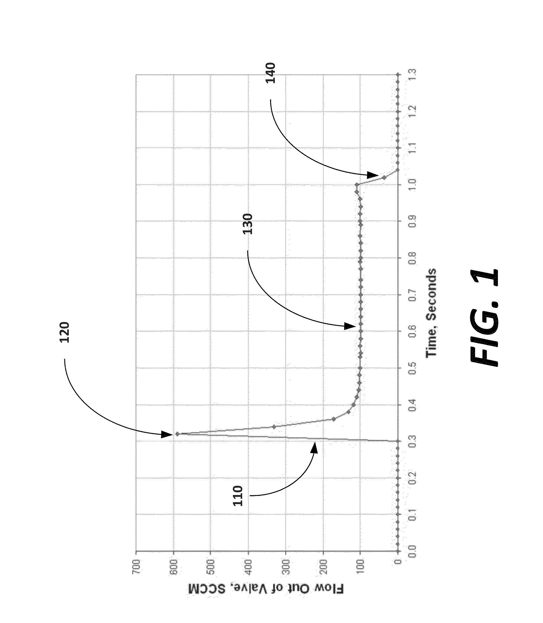
Unfortunately, as shown in FIG. 1, when the on-off valve is opened at the beginning of an on cycle, the built up pressure in the accumulation volume initially causes a large flow of gas that quickly decays in magnitude to the steady state flow of the MFC as the stored pressure and mass is released, due to a small time constant from a low flow resistance (or nearly no flow resistance) in the on-off valve.
During normal processing of semiconductors, instrumentation to observe the output wave in not available and thus actual flow profiles are unseen and often unknown.
The initial spike 120, however, is undesirable because it introduces an unseen, unintended, and uncontrolled event.
In addition, the presence of this large transient gas flow has been largely unknown and generally, large overshoots in gas flow are undesirable.

Method used


Image

  • Gas delivery system for outputting fast square waves of process gas during semiconductor processing
  • Gas delivery system for outputting fast square waves of process gas during semiconductor processing
  • Gas delivery system for outputting fast square waves of process gas during semiconductor processing

Examples


Embodiment Construction

[0025]Gas delivery apparatus, and methods, to output a process gas as rapid square waves by increasing a time constant of a gas flowing to a process during an on cycle, by installing flow restrictor having a specific high impedance.

[0026]Square Wave Output Characteristics of a Gas Delivery System

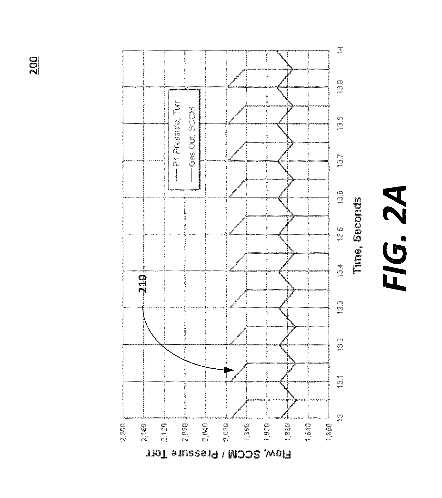
[0027]FIG. 2A is a graph 200 illustrating the results of a computer simulation showing a series of square output waves produced by a gas delivery system with a properly sized and installed flow restrictor, in accordance with an embodiment of the present invention. Given the gas pressures used and the conductance of the on-off valves typically used with the current method, the addition of a flow restrictor can increases the flow impedance and hence the a time constant of the flow out of the on-off valve up to, for example, 60,000 times. The resulting square waves (such as square wave 210) are characterized by an on cycle at a desired magnitude of flow (and only minor decay which is affected b...


PUM


Abstract

A wave generation component during an off cycle when the on-off valve is closed to build pressure from the process gas in an accumulation volume. During an on cycle when the on-off valve is open the wave generation component releases the process gas according to a time constant. A flow restrictor installed downstream in a throat of the on-off valve, outputs the rapid square waves to the conduit at a predefined magnitude. The flow restrictor is selected to have an impedance that is high enough to significantly raise the time constant during the on cycle such that pressure decay in each square wave pulse over the on cycle decreases to within a tolerance, wherein the time constant is at least in part a function of the flow restrictor impedance.

Description

CROSS-REFERENCE TO RELATED APPLICATIONS[0001]This application claims the benefit of priority under 35 U.S.C. 119(e) to U.S. Application No. 61 / 850,503, filed Feb. 15, 2013, entitled MEANS AND METHOD OF DELIVERING “FAST SQUARE” PULSES OF GAS, by Daniel T. Mudd et al., the contents of which are hereby incorporated by reference in its entirety.FIELD OF THE INVENTION[0002]The invention relates generally to semiconductor processing, and more specifically, improved gas delivery of process gas using mass flow controllers (MFCs) and electric regulators.BACKGROUND OF THE INVENTION[0003]Mass flow controllers (MFCs) and electronic regulators are important components of delivering process gasses (e.g., N2, O2, SF6, C4F8 . . . etc.) for semiconductor fabrication. Of particular interest are the atomic layer deposition (ALD) and three-dimensional integrated circuit (3DIC) processes which require the rapid and repeated changing or the gas species in the process chamber thousands of times to achieve...

Claims


Application Information

Patent Timeline
IPC IPC(8): G05D7/06H01L21/67
CPCH01L21/67017G05D7/0617G05D7/0647F15B21/12Y10T137/0441Y10T137/86389
Inventor MUDD, DANIEL T.MUDD, PATTI J
Owner ICHOR SYST INC
Learn More