Elevator system

Inactive Publication Date: 2014-08-21
KONE CORP
View PDF19 Cites 5 Cited by
  • Summary
  • Abstract
  • Description
  • Claims
  • Application Information

AI Technical Summary

Benefits of technology

The invention is about a new elevator system that saves space in the hoistway and improves efficiency by using a thin traction member and a separate safety device. This also reduces the weight that needs to be supported by the safety device, which can be brought into interaction with the load-receiving part at the bottom of the hoistway. The load-receiving part is moved along a vertical path of movement and the traction member is suspended on the load-receiving part and on the counterweight for exerting a downward-pulling force on the load-receiving part. The weight of the elevator car / counterweight is not exerted directly on the traction member, which simplifies the dimensioning of the traction member and the drive unit transmitting power to it. The load-receiving part is pulled symmetrically, which prevents detrimental torsion. The mechanical safety device can be brought into interaction with the load-receiving part when it reaches the bottom or the top, depending on the direction of movement. Overall, the invention improves elevator efficiency and saves space.

Problems solved by technology

This type of solution saves built space.
Fitting a new elevator system into the existing old elevator hoistway can be challenging owing to, inter alia, the small top safety spaces and small bottom safety spaces of the elevator hoistway.

Method used


Image

  • Elevator system
  • Elevator system
  • Elevator system

Examples


Embodiment Construction

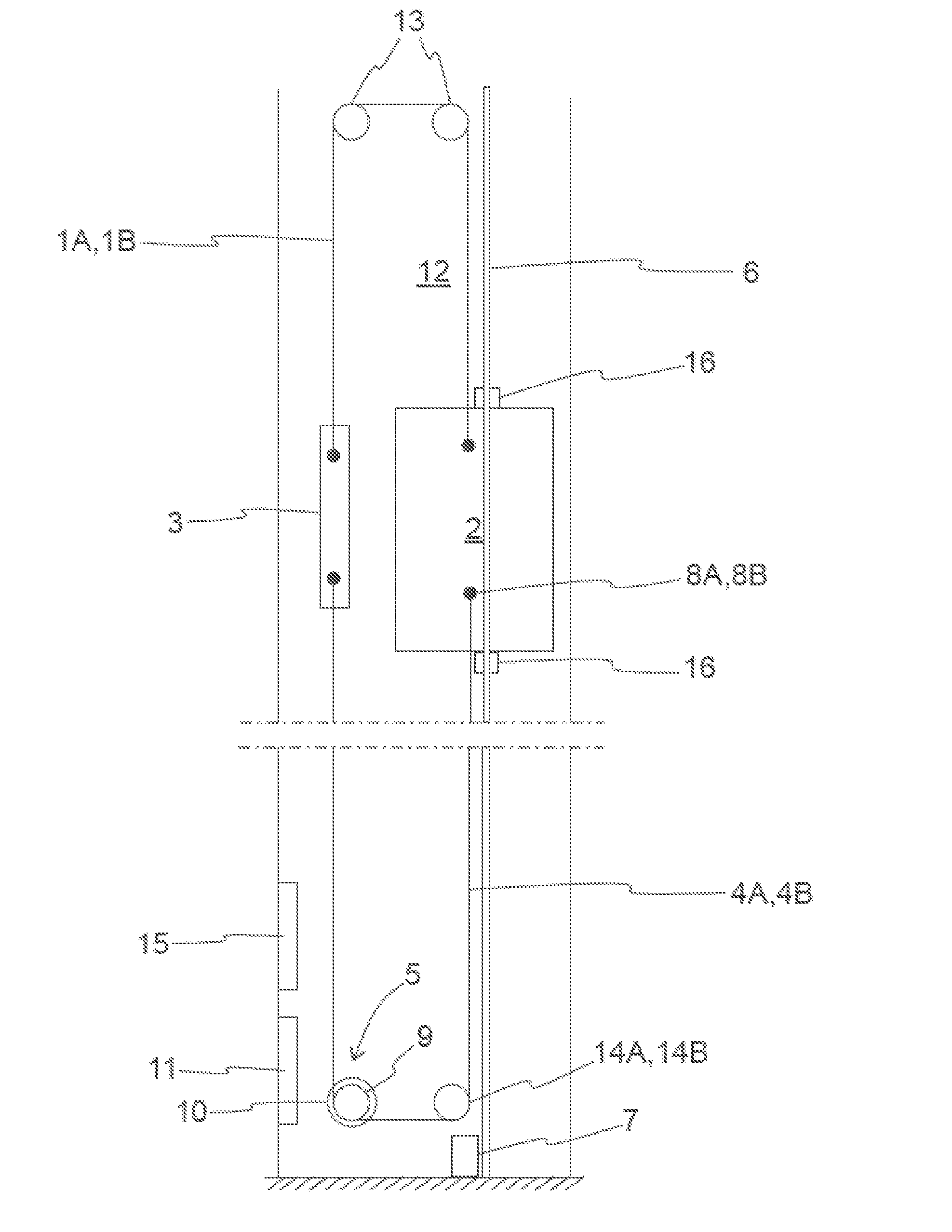
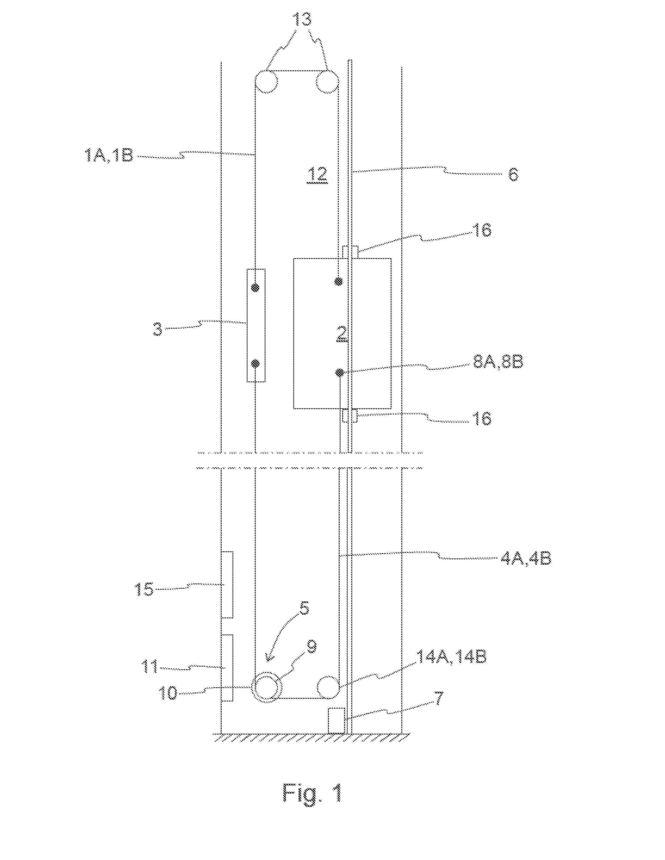
[0031]FIG. 1 presents a schematic side view of an embodiment of an elevator system having 1:1 suspension. Additionally, FIGS. 2 and 3 present the embodiment of FIG. 1 as viewed from directly below and obliquely from above. In the elevator system of FIG. 1 the elevator car 2 and the counterweight 3 are suspended in the elevator hoistway 12 with parallel suspension ropes 1A, 1B, which travel via diverting pulleys 13 fixed in a manner allowing rotation to the top part of the elevator hoistway. Steel ropes, composite ropes or a belt in which load-bearing strands such as e.g. metal strands, e.g. steel strands, or non-metallic strands, for instance glass fiber strands, are configured inside a matrix made of polyurethane or corresponding, can, inter, alia, be used as suspension ropes 1A, 1B. In this embodiment of the invention the suspension ropes 1A, 1B are fixed to the elevator car 2 and to the counterweight 3 from suspension points, which are disposed on opposite sides of the elevator c...


PUM


Abstract

An elevator system includes an elongated suspension member, a load-receiving part suspended on the suspension member, a counterweight suspended on the suspension member for supporting the load-receiving part, an elongated traction member for exerting a pulling force on the load-receiving part and on the counterweight, a drive unit, with which the load-receiving part is driven by pulling the traction member and also one or more guide rails, along the path of movement determined by which the load-receiving part is moved. The drive unit is disposed to the side of the path of movement of the load-receiving part.

Description

FIELD OF THE INVENTION [0001]The invention relates to elevator systems, more particularly on and placement of elevator components in an elevator system.BACKGROUND OF THE INVENTION[0002]Elevators are used for lifting a load in varying operating sites. An elevator usually comprises an elevator car, a lifting platform or a corresponding load-receiving part, with which a load is transferred. The load-receiving part, with counterweight, is suspended on an elongated suspension member that is continuous in the vertical direction, such as on a rope or belt. The load-receiving part is moved along a vertical track guided by a guide rail.[0003]The driving force for moving the load-receiving part is usually produced with a separate drive unit. The drive unit comprises an electric motor. Some elevators comprise, in addition to the aforementioned suspension member, a separate elongated traction member, such as a belt having friction traction or tooth traction, which transmits the driving force pr...

Claims


Application Information

Patent Timeline
IPC IPC(8): B66B11/00
CPCB66B11/0045B66B11/009B66B11/0206
Inventor KALLIONIEMI, ANTTIPLATHIN, ANTTI
Owner KONE CORP
Why Eureka
Try Eureka