In-wheel motor drive assembly

a technology of in-wheel motors and drive parts, which is applied in the direction of electric devices, gearing details, vehicle sub-unit features, etc., can solve the problems of affecting the motor, deteriorating the efficiency of electric motors,

Inactive Publication Date: 2014-08-21
NTN CORP
View PDF15 Cites 6 Cited by
  • Summary
  • Abstract
  • Description
  • Claims
  • Application Information

AI Technical Summary

Benefits of technology

[0019]In this arrangement, the oil guide passage may comprise an annular groove formed in the outer surface of the first disk portion facing the partition wall at the inner peripheral portion of the first disk portion, the annular groove having an L-shaped section, and through-holes communicating at ends of the respective through-holes with the radially outer edge of the annular groove, and extending toward the end surfaces of the respective bearings rotatably supporting the planetary gears. With this arrangement, the annular groove serves as an oil reservoir. Since the carrier is rotating about the rotor shaft, lubricating oil in the annular groove flows toward the bearings supporting the planetary gears due to centrifugal force. This makes it possible to more efficiently lubricate the bearings supporting the planetary gears.
[0020]Preferably, the oil guide surface has its small-diameter end located in the annular groove so that, lubricating oil flowing down along the inner surface of the partition wall can more reliably flow into the annular groove.
[0019]In this arrangement, the oil guide passage may comprise an annular groove formed in the outer surface of the first disk portion facing the partition wall at the inner peripheral portion of the first disk portion, the annular groove having an L-shaped section, and through-holes communicating at ends of the respective through-holes with the radially outer edge of the annular groove, and extending toward the end surfaces of the respective bearings rotatably supporting the planetary gears. With this arrangement, the annular groove serves as an oil reservoir. Since the carrier is rotating about the rotor shaft, lubricating oil in the annular groove flows toward the bearings supporting the planetary gears due to centrifugal force. This makes it possible to more efficiently lubricate the bearings supporting the planetary gears.
[0025]According to the present invention, since a reduction mechanism chamber is provided outside a motor chamber defined in the motor case so as to be isolated from the motor chamber, the reduction mechanism is mounted in the reduction mechanism chamber, oil for lubricating the reduction mechanism is stored in the reduction mechanism chamber, a partition wall between the motor chamber and the reduction mechanism chamber is formed with a tapered oil guide surface at a central portion of the partition wall, and the tapered oil guide surface is configured to guide oil splashed up by the planetary gears and flowing down along an inner surface of the partition wall while the planetary gears are rotating and revolving, toward a bearing supporting the rotor shaft and the output shaft so as to be rotatable relative to each other, it is possible to lubricate the reduction mechanism and the bearing with oil without reducing efficiency of the electric motor.

Problems solved by technology

Since it is necessary to use oil having a high viscosity in order to lubricate the reduction mechanism, the efficiency of the electric motor may deteriorate due to the viscous resistance of oil.
Also, since metal dust generated due to wear of gears of the reduction mechanism is mixed into oil which is used to cool the electric motor, metal dust may enter the electric motor, thus detrimentally affecting the motor.

Method used


Image

  • In-wheel motor drive assembly
  • In-wheel motor drive assembly
  • In-wheel motor drive assembly

Examples


Embodiment Construction

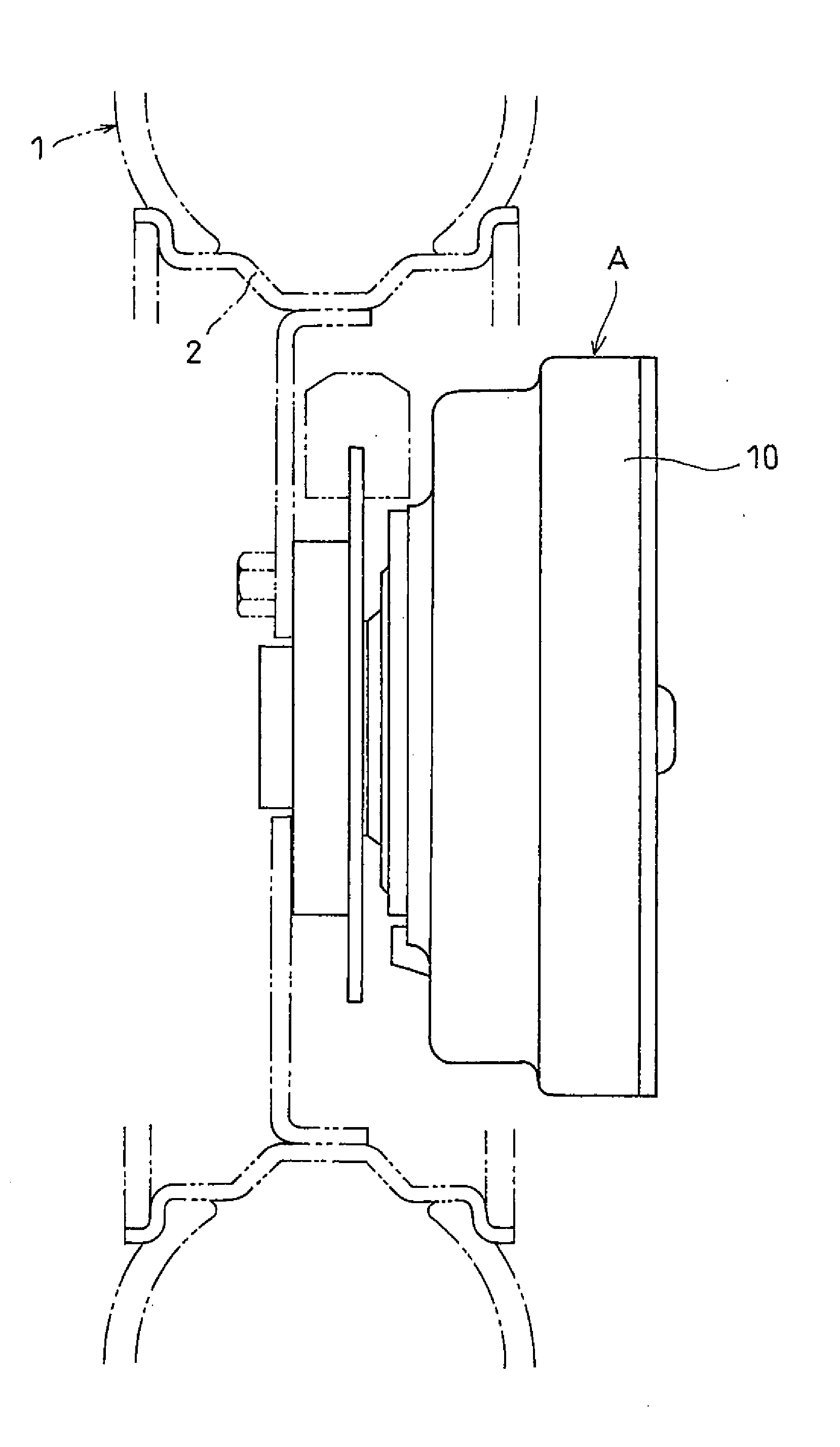
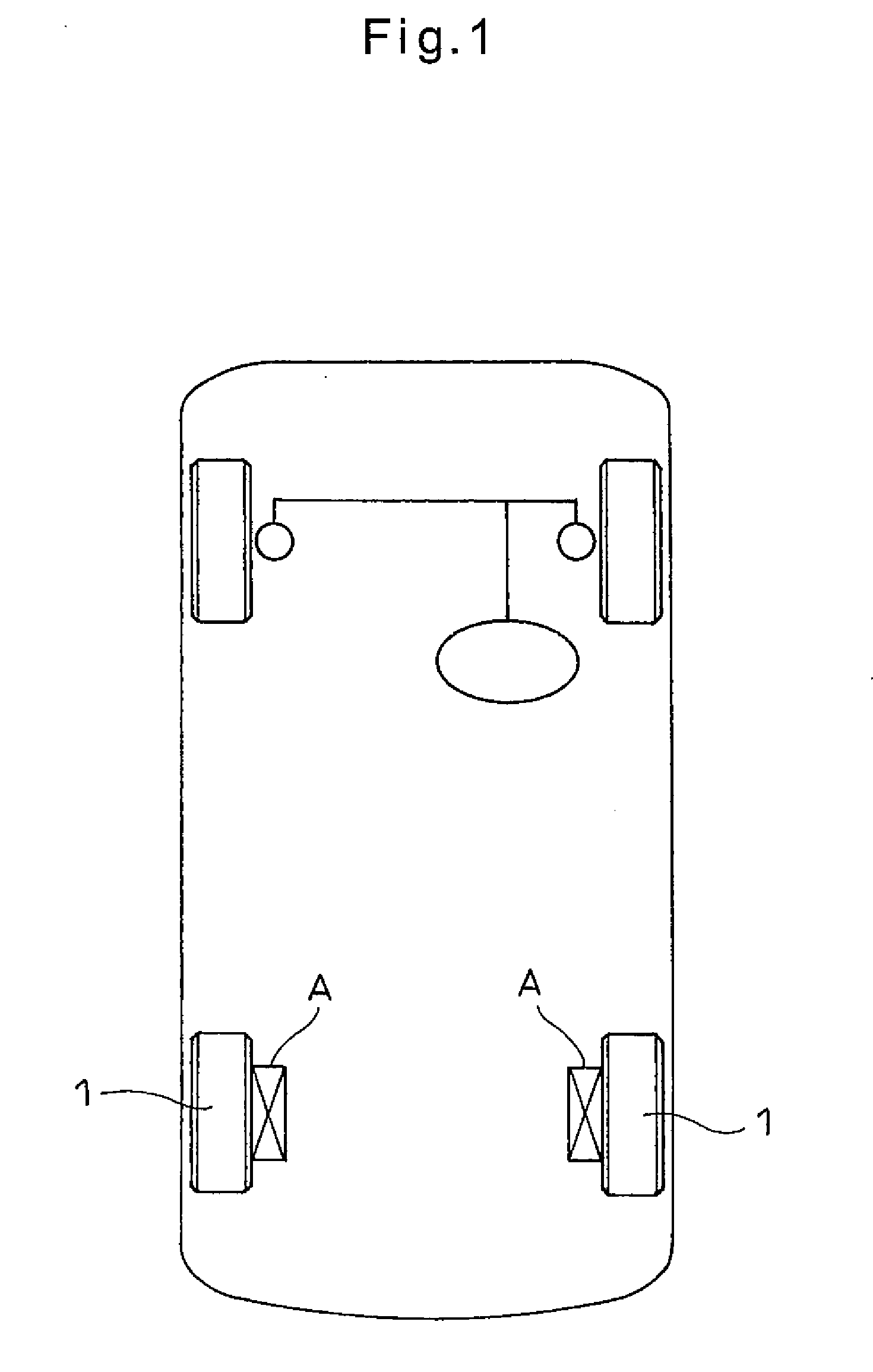
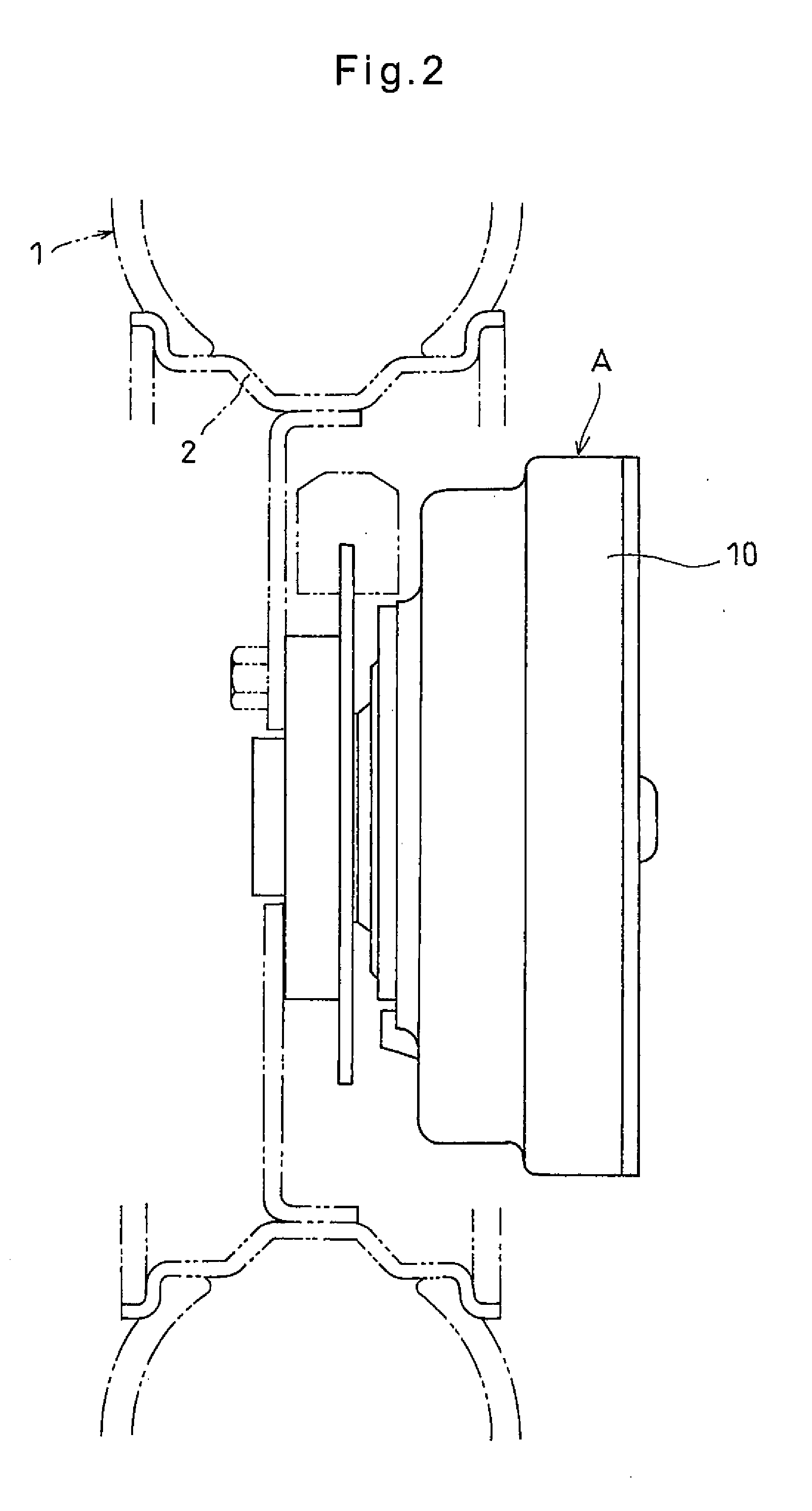
[0039]Now, the in-wheel motor drive assembly A embodying the present invention is described with reference to the drawings. As shown in FIG. 2, the in-wheel motor drive assembly A is mounted in the wheel body of a drive wheel 1.

[0040]As shown in FIG. 3, the in-wheel motor drive assembly A includes a motor case 10, an electric motor 30 mounted in the motor case 10, a reduction mechanism 40 for reducing the rotation of the electric motor 30 and outputting the thus reduced rotation, and a wheel bearing 60 rotatably supporting an output shaft 41 of the reduction mechanism 40.

[0041]The motor case 10 comprises a cylindrical case body 11 and a cover 12 closing an opening of the case body 11 at one end thereof. The cover 12 is formed with a cylindrical portion 12a fitted in the opening at one end of the case body 11. A seal ring 13 is mounted and seals between the fitting surfaces of cylindrical portion 12a and the case body 11.

[0042]The case body 11 has an annular end plate portion 14 at t...


PUM


Abstract

An in-wheel motor drive assembly includes a motor case defining a motor chamber and a reduction mechanism chamber provided on one side of and isolated from the motor chamber by a partition wall. An electric motor is mounted in the motor chamber. A planetary gear reduction mechanism is mounted in the reduction mechanism chamber, and reduces the rotation of the electric motor and outputs the reduced rotation to a hub ring. The reduction mechanism is lubricated by lubricating oil stored in the reduction mechanism chamber. A tapered oil guide surface is formed at the center of the inner surface of the partition wall facing the reduction mechanism chamber. The oil guide surface guides lubricating oil splashed up by the rotating reduction mechanism and flowing down along the inner surface of the partition wall, onto the rotor shaft of the electric motor, thereby lubricating bearings mounted on the rotor shaft.

Description

TECHNICAL FIELD[0001]This invention relates to an in-wheel motor drive assembly for driving a drive wheel of a vehicle.BACKGROUND ART[0002]FIG. 1 schematically shows an in-wheel motor type electric vehicle. The electric vehicle shown has two motor drive assemblies A each including an electric motor as a driving source and mounted, respectively, in the pair of right and left rear wheels 1 as drive wheels such that the rear wheels 1 can be individually driven by the motor drive assemblies A.[0003]Motor drive assemblies A used in such in-wheel motor type electric vehicles include an electric motor, a reduction mechanism for reducing the rotation of the rotor shaft of the electric motor, and a drive axle driven from the reduction mechanism. The rotation of the drive axle is transmitted to one of the rear wheels through a hub ring supported by the drive axle.[0004]Since such a motor drive assembly is mounted in a rear wheel, it axial length has to be sufficiently short. In order to minim...

Claims


Application Information

Patent Timeline
Patent Type & Authority Applications(United States)
IPC IPC(8): B60K7/00
CPCB60K2007/0038B60K7/0007B60K17/046B60K2007/0092F16H57/0457F16H57/0471F16H57/0476F16H57/0486B60L3/0061B60L15/2036B60L15/2054B60L2220/44B60L2220/50B60L2240/36B60L2240/421B60L2240/486B60Y2306/03Y02T10/64Y02T10/72
Inventor YAMAMOTO, KENISHIKAWA, AIKO
Owner NTN CORP
Why Eureka
Try Eureka