Determination of a pulse sequence for a magnetic resonance system

a magnetic resonance system and pulse sequence technology, applied in the direction of magnetic measurement, geological measurement, reradiation, etc., can solve the problems of requiring programming tools that are dependent on the method, and requiring highly specialized programmers, so as to facilitate sequence programming

Inactive Publication Date: 2014-08-21
SIEMENS HEALTHCARE GMBH
View PDF3 Cites 11 Cited by
  • Summary
  • Abstract
  • Description
  • Claims
  • Application Information

AI Technical Summary

Benefits of technology

[0044]In the method according to the invention, the k-space trajectory node points and / or the pulse sequence (possibly including the auxiliary moments) are advantageously determined or defined using an apparatus-independent programming language. The determination or definition of the k-space trajectory node points and / or of the pulse sequence (possibly including the auxiliary moments) preferably takes place using a scripting language. In other words, the trajectory node point determination unit and / or the pulse sequence determination unit can be realized via an apparatus-independent programming language (in particular a scripting language). This has the advantage that less experienced programmers (for example on site at a clinic) can also still modify the automatic method to determine the k-space trajectory node points or to determine the pulse sequence, wherein no system-specific knowledge is required. Such a script-controlled definition of k-space trajectories, for example with prior pre-pulses, radio-frequency signals and radio-frequency readout cycles, crushers, etc. that are switched in parallel or succession, thus facilitates the sequence programming not only internally at the system manufacturer, but also at their customers or, respectively, later users of the systems.

Problems solved by technology

This method is therefore relatively complicated, and requires highly specialized programmers and normally special, apparatus-dependent programming tools.

Method used


Image

  • Determination of a pulse sequence for a magnetic resonance system
  • Determination of a pulse sequence for a magnetic resonance system
  • Determination of a pulse sequence for a magnetic resonance system

Examples


Embodiment Construction

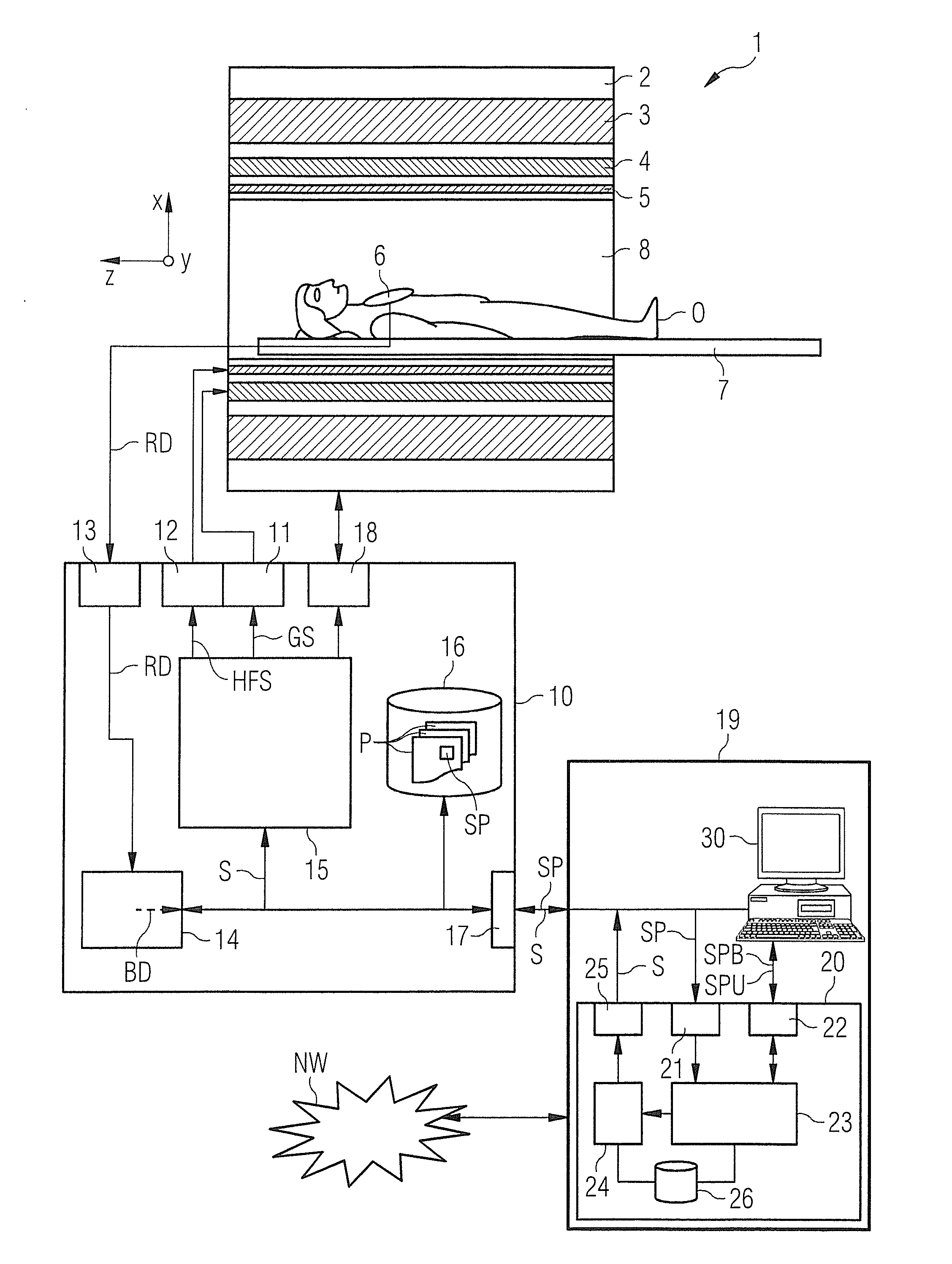
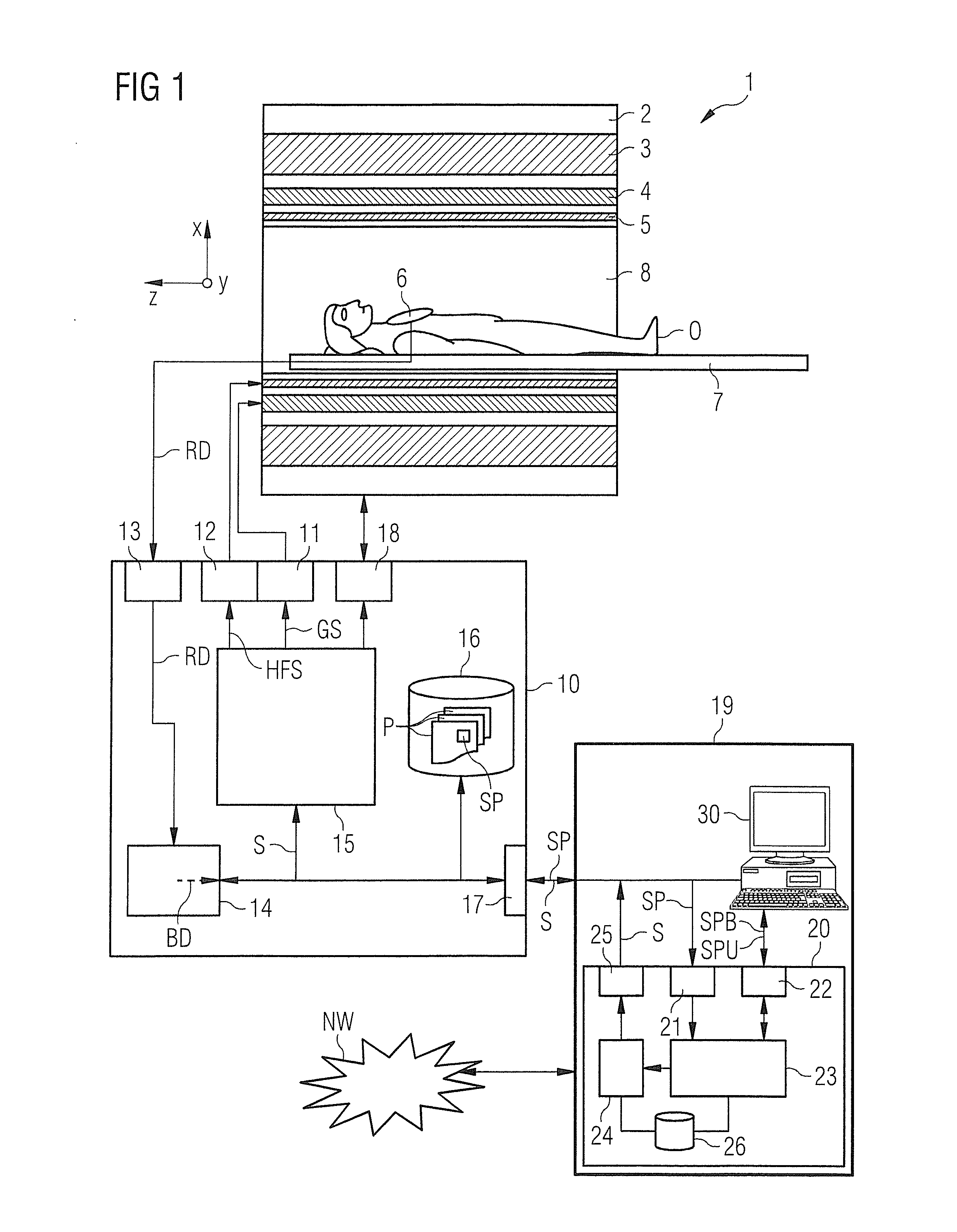
[0050]A magnetic resonance system 1 according to the invention is schematically depicted in FIG. 1. The system includes the actual magnetic resonance scanner 2 with an examination space or patient tunnel 8 located therein. A bed 7 can be driven into this patient tunnel 8 so that a patient O or test subject lying thereupon during an examination can be borne at a defined position within the magnetic resonance scanner 2 relative to the magnet system and radio-frequency system arranged therein, or can also be moved between different positions during a measurement.

[0051]Basic components of the magnetic resonance scanner 2 are a basic field magnet 3, a gradient system 4 with magnetic field gradient coils to generate magnetic field gradients in x-, y- and z-direction, and a whole-body radio-frequency coil 5. The magnetic field gradient coils in the x-, y- and z-direction are controllable independently of one another so that gradients can be applied in arbitrary logical spatial directions (...


PUM


Abstract

In a method and a pulse sequence determination device to determine a pulse sequence for a magnetic resonance system, control protocol parameter values are initially acquired. A determination of k-space trajectory node points within k-space then takes place in a processor on the basis of the control protocol parameter values. The determination of the pulse sequence then takes place on the basis of the k-space trajectory node points. A method for operating a magnetic resonance system uses such a pulse sequence, and a magnetic resonance system embodies such a pulse sequence determination device.

Description

BACKGROUND OF THE INVENTION[0001]1. Field of the Invention[0002]The invention concerns a method and a pulse sequence determination device to determine a pulse sequence for a magnetic resonance system. Moreover, the invention concerns a method to operate a magnetic resonance system using such a pulse sequence, as well as a magnetic resonance system with a radio-frequency transmission device that is designed in order to emit a radio-frequency pulse train to implement a desired measurement on the basis of a predetermined pulse sequence, and to emit a gradient pulse train via the gradient system, in coordination with the emission of the radio-frequency pulse train.[0003]2. Description of the Prior Art[0004]In a magnetic resonance system also called a magnetic resonance tomography system, the body to be examined is typically exposed to a relatively high basic magnetic field (for example of 1, 5, 3 or 7 Tesla) with the use of a basic field magnet system. A magnetic field gradient is addit...

Claims


Application Information

Patent Timeline
Patent Type & Authority Applications(United States)
IPC IPC(8): G01R33/54
CPCG01R33/543G01R33/482G01R33/4824
Inventor GRODZKI, DAVIDHEISMANN, BJOERN
Owner SIEMENS HEALTHCARE GMBH
Why Eureka
Try Eureka