
Correction data generation method, correction data generation system, and image quality adjustment technique using the method and system

a technology of correction data and image quality, applied in the direction of instruments, static indicating devices, etc., can solve the problems of liquid crystal panel, organic el panel and similar display panel display panel display panel display panel unevenness, luminance unevenness, etc., to suppress the influence of photon shot noise, improve the image quality of the display panel, and high accuracy of correction data

Inactive Publication Date: 2014-08-21
IIX
View PDF8 Cites 17 Cited by
  • Summary
  • Abstract
  • Description
  • Claims
  • Application Information

AI Technical Summary

Benefits of technology

The patent invention generates accurate correction data while reducing the impact of photon shot noise, which improves the image quality of a display panel.

Problems solved by technology

It is commonly known that a liquid crystal panel, an organic EL panel and similar display panels exhibit unevenness in display, such as luminance unevenness and color unevenness, due to manufacturing variations such as unevenness in cell gaps and unevenness in the brightness of a backlight.

Method used


Image

  • Correction data generation method, correction data generation system, and image quality adjustment technique using the method and system
  • Correction data generation method, correction data generation system, and image quality adjustment technique using the method and system
  • Correction data generation method, correction data generation system, and image quality adjustment technique using the method and system

Examples


embodiment 1

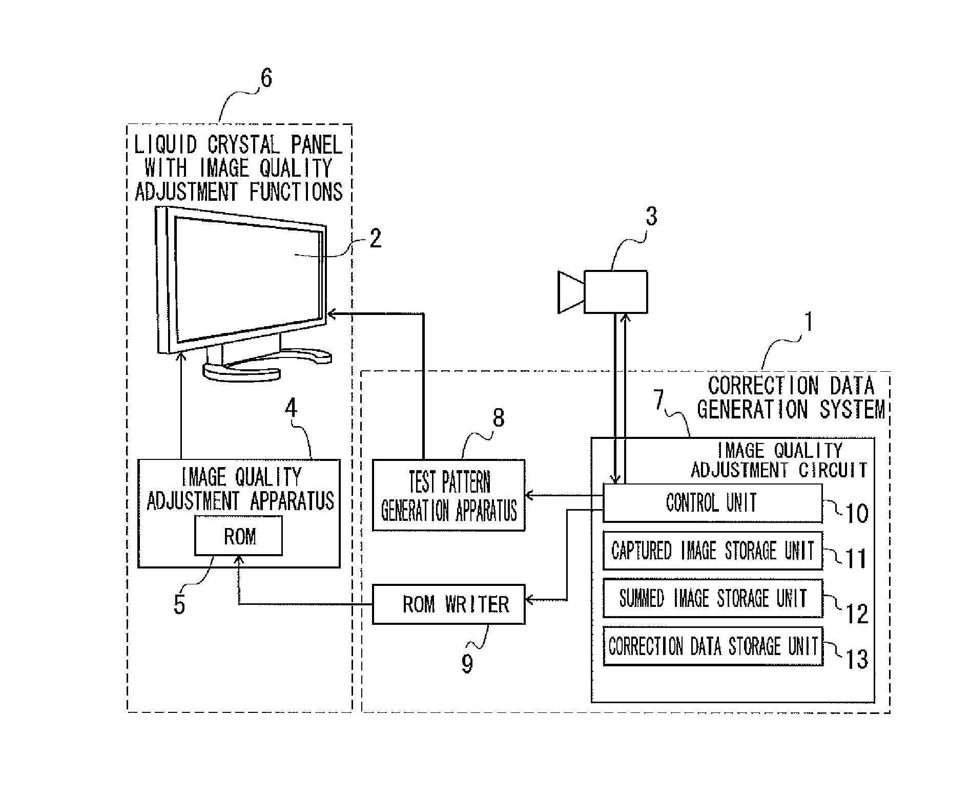
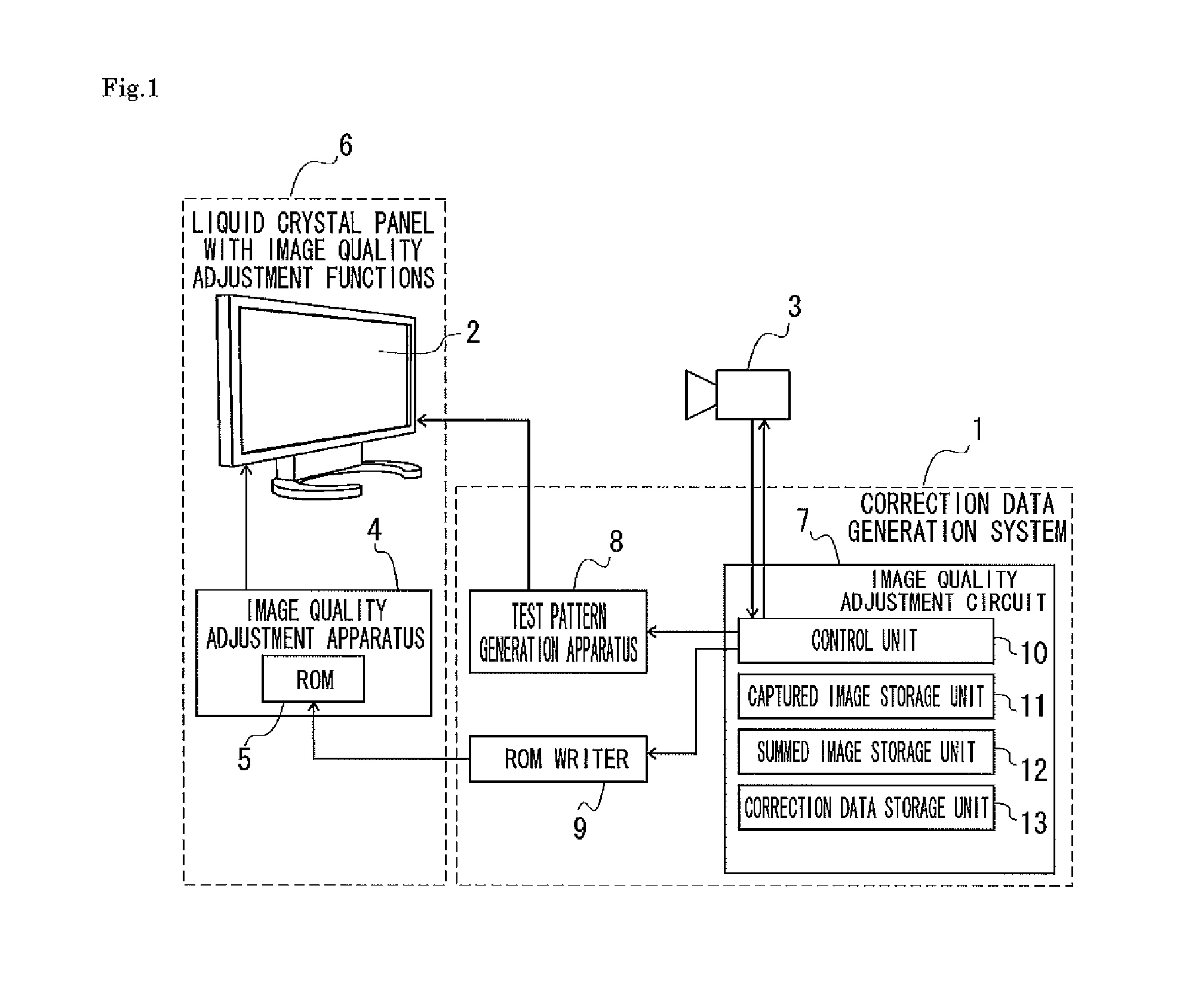
[0043]FIG. 1 illustrates a correction data generation system pertaining to the present embodiment. A correction data generation system 1 displays test patterns on a liquid crystal panel 2, captures the displayed test patterns with a black-and-white camera 3 including a solid-state imaging device, and generates correction data for reducing unevenness in display of the liquid crystal panel 2. The generated correction data is stored in a ROM (non-volatile memory) 5 in an image quality adjustment circuit 4. A liquid crystal panel 6 with image quality adjustment functions is manufactured by mounting this image quality adjustment circuit 4 on the liquid crystal panel 2. In the liquid crystal panel 6 with image quality adjustment functions, the image quality adjustment circuit 4 corrects an image signal input to the liquid crystal panel 2 (input signal) with reference to the correction data stored in the ROM 5. As a result, unevenness in display of the liquid crystal panel 2 is reduced, an...

embodiment 2

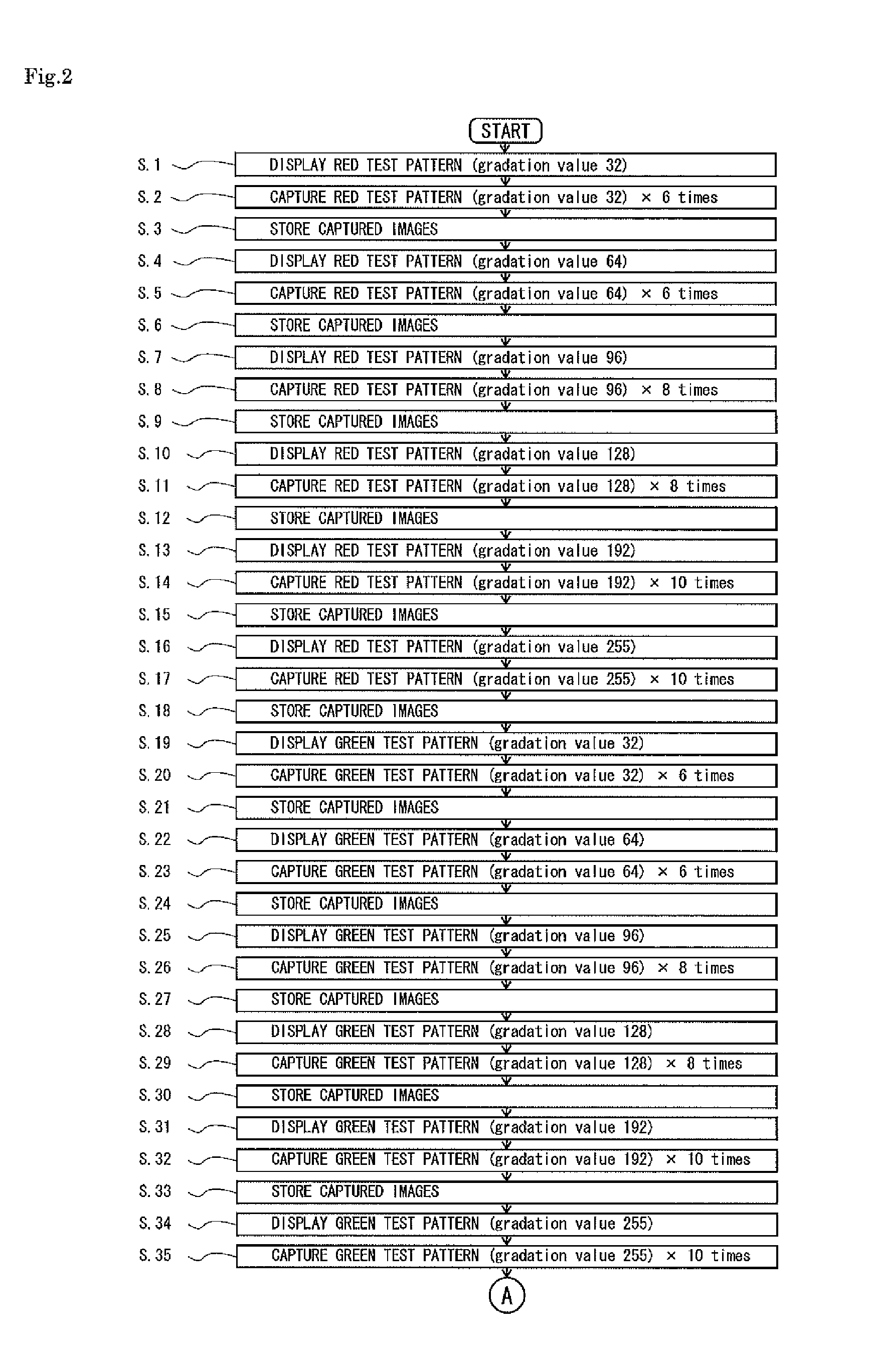
[0058]The present embodiment provides another method for generating correction data in the correction data generation system 1.

[0059]As illustrated in FIG. 4, the control unit 10 first instructs the test pattern generation apparatus 8 to transmit an 8-bit test pattern display signal (RGB signal) to the liquid crystal panel 2 so as to display white test patterns on the liquid crystal panel 2 (step 71). These white test patterns are realized by all pixels in the liquid crystal panel 2 displaying white (depending on the luminance, it may look gray) through emission of RGB light. In step 71, a white image (gray image) with a gradation value of 32 is displayed across the liquid crystal panel 2.

[0060]Next, the control unit 10 captures the liquid crystal panel 2 displaying the white test patterns with the camera 3 six times (step 72), and stores the captured images in the captured image storage unit 11 (step 73).

[0061]Subsequently, the control unit 10 changes the gradation value of the whi...


PUM


Abstract

Provided is a correction data generation method that can generate highly accurate correction data while suppressing the influence of photon shot noise. According to the correction data generation method of the present invention, test patterns are displayed on a liquid crystal panel (2) in units of specific gradation values, the displayed test patterns are captured by a camera (3) a plurality of times for each specific gradation value, and a summed image is generated for each specific gradation value by summing a plurality of captured images of the test patterns. Based on the summed image for each specific gradation value, correction data is generated for reducing unevenness in display of the liquid crystal panel (2) through correction of a signal input to the liquid crystal panel (2).

Description

CROSS REFERENCE TO RELATED APPLICATIONS[0001]This Application is continuation of and claims the benefit of priority from the prior PCT Application No. PCT / JP2013 / 053919, filed. on Feb. 19, 2013, the entire contents of which are incorporated herein by reference.TECHNICAL FIELD[0002]The present invention relates to a correction data generation method and a correction data generation system that capture a display panel with a camera so as to generate correction data for reducing unevenness in display of the display panel through correction of a signal input to the display panel, and also relates to an image quality adjustment technique using such method and system.BACKGROUND ART[0003]It is commonly known that a liquid crystal panel, an organic EL panel and similar display panels exhibit unevenness in display, such as luminance unevenness and color unevenness, due to manufacturing variations such as unevenness in cell gaps and unevenness in the brightness of a backlight. When each pixel...

Claims


Application Information

Patent Timeline
IPC IPC(8): G09G3/36
CPCG09G3/3607G09G3/2003G09G3/3611G09G2320/0233G09G2320/0693G09G2360/145
Inventor MURASE, HIROSHIIMOTO, MASAYOSHI
Owner IIX
Learn More