Inverter system and driving method for an inverter system

a technology of inverter system and driving method, which is applied in the direction of power conversion system, climate sustainability, efficient power electronics conversion, etc., can solve the problems of inverter use, negatively affecting the service life of inverter, etc., and achieves low output voltage, efficient driving, and improved network quality

Inactive Publication Date: 2014-08-21
ROBERT BOSCH GMBH
View PDF11 Cites 15 Cited by
  • Summary
  • Abstract
  • Description
  • Claims
  • Application Information

AI Technical Summary

Benefits of technology

[0017]One specific embodiment of the present invention comprises an inverter system which is provided for feeding energy into an electric power network or for improving the network quality.
[0018]One additional specific embodiment of the present invention comprises an electric drive having an inverter system according to the present invention. Electric drives in particular also require relatively low output voltages and / or operation having a cos(Φ) of relatively low magnitude. By operating the inverter system according to the present invention, particularly efficient driving may be achieved.

Problems solved by technology

Furthermore, inverters are also used, for example, in uninterruptible power supplies (UPSs).
In addition to lower efficiency, these losses also result in thermal loading of the inverter, thus requiring increased cooling and also negatively effect the service life of the inverter.

Method used


Image

  • Inverter system and driving method for an inverter system
  • Inverter system and driving method for an inverter system
  • Inverter system and driving method for an inverter system

Examples


Embodiment Construction

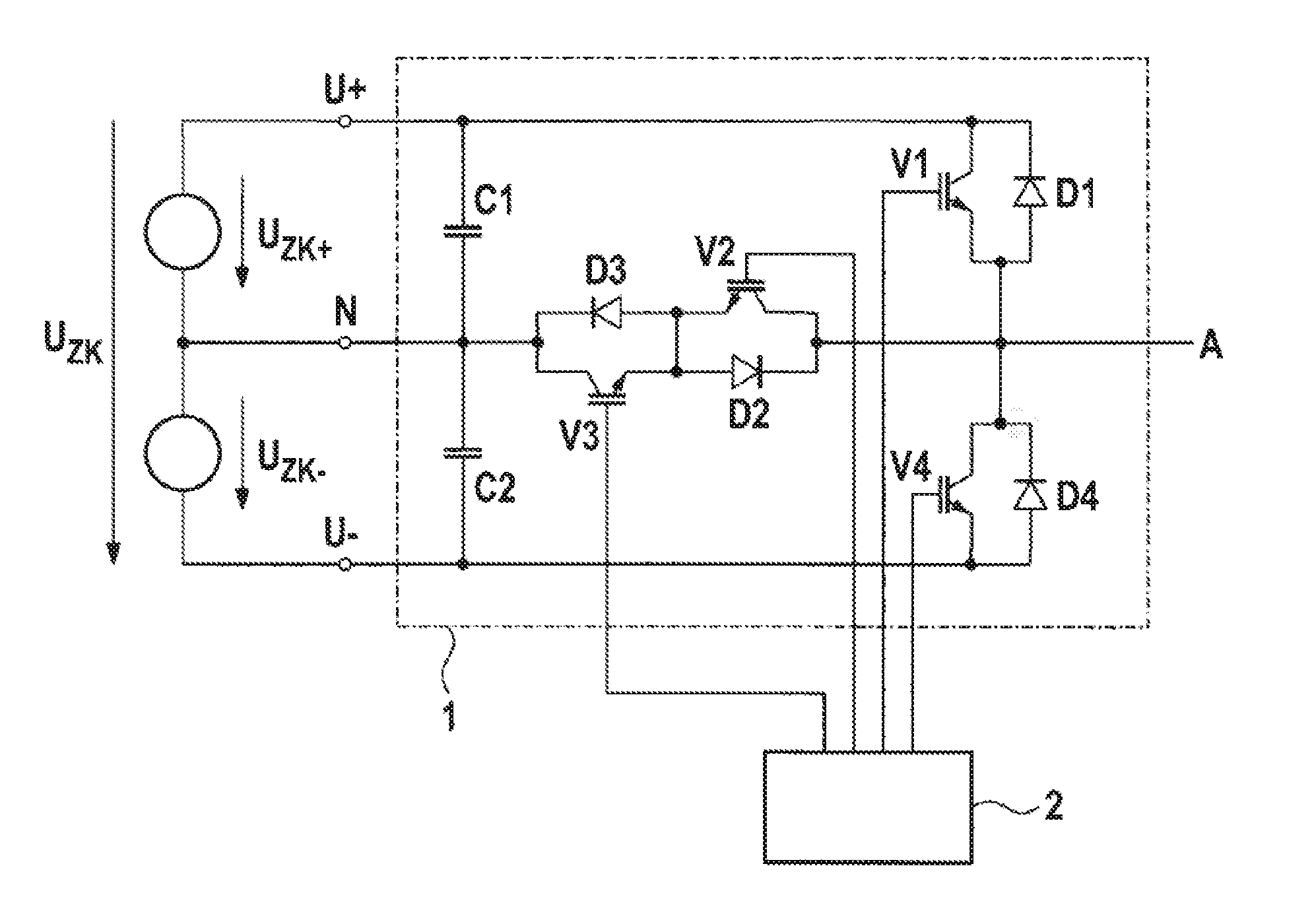
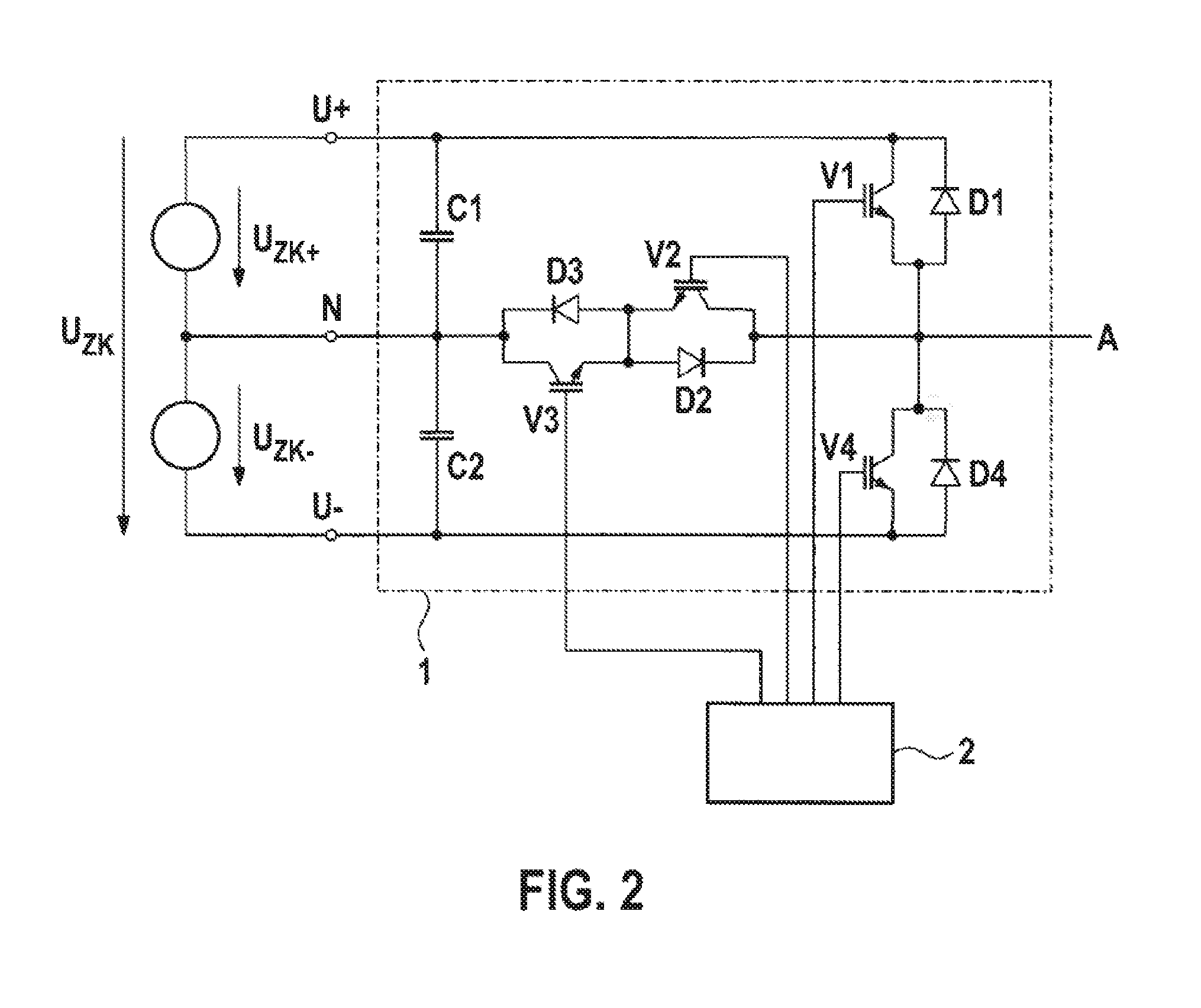
[0025]FIG. 2 shows one embodiment of a three-level inverter by way of example. The upper bridge arm of the inverter is connected to the terminal U+ for the positive input voltage UZK+. The lower bridge arm is connected to the terminal U− for the negative input voltage UZK−. The center bridge arm is connected to the input terminal N for the center tap of the input voltage. Half the intermediate circuit voltage UZK is respectively applied between the terminal U+ and N and between the terminal N and U− as the input voltage UZK+ and UZK−. The inverter 1 has a first intermediate-circuit capacitor C1 between the terminal U+ and the terminal N, and a second intermediate-circuit capacitor C2 between the terminal N and U−. The inverter 1 furthermore has the four switching elements V1 to V4, which are driven via a control device 2. A pulsed output voltage is thus present at the output terminal A. The diodes D1 to D4 are each connected inversely parallel to the four switching elements V1 to V4...


PUM


Abstract

The present invention provides optimized driving of an inverter device. The inverter of such an inverter device may alternatively be driven in two-level operation or in three-level operation. Through a suitable selection of the driving method, the semiconductor losses in the inverter may be minimized and the thermal loading of the components used may be controlled in a targeted manner. Using the provided operating method for an inverter, more efficient and more protective inverter operation is possible, even at low output voltages and highly inductive or capacitive loading.

Description

BACKGROUND OF THE INVENTION[0001]The present invention relates to an inverter system and a driving method for operating an inverter system.[0002]Electric inverters which generate a single-phase or multiphase AC voltage from a DC voltage are known. For example, such inverters are used to feed electric energy from regenerative energy sources such as a photovoltaic system into an electric power network. Furthermore, inverters are also used, for example, in uninterruptible power supplies (UPSs). In addition, inverter systems are also used for controlling electric drives, for example, in electric vehicles.[0003]In the design of inverter circuits, a distinction is made between two-point circuits or two-level circuits on the one hand and three-point circuits or three-level circuits on the other hand. FIG. 1 shows an example of a two-level circuit of a single-phase inverter. At the input of this inverter, the intermediate circuit voltage UZK is present between the points U+ and U−. The targ...

Claims


Application Information

Patent Timeline
Patent Type & Authority Applications(United States)
IPC IPC(8): H02M7/5387
CPCH02M7/5387H02M7/487H02M2001/0054Y02B70/10H02M1/0054
Inventor SPANOS, KONSTANTINSTEINBUCH, HARTMUT
Owner ROBERT BOSCH GMBH
Why Eureka
Try Eureka