Electrical contact-making system

a contact-making system and contact-making technology, applied in the direction of insulating conductors, coupling device connections, contact members penetrating/cutting insulation/cable strands, etc., can solve the problems of only meeting the requirements insufficiently, and achieve the effect of improving the impermeability of the contact-making system and increasing the operating temperature rang

Active Publication Date: 2014-08-21
WIELAND ELECTRIC
View PDF14 Cites 10 Cited by
  • Summary
  • Abstract
  • Description
  • Claims
  • Application Information

AI Technical Summary

Benefits of technology

[0004]It is accordingly an object of the invention to provide an electrical contact-making system, which overcomes the hereinafore-mentioned disadvantages of the heretofore-known systems of this general type, which increases the operating temperature range of such a contact-making system and which, at the same time, improves the impermeability of the contact-making system.

Problems solved by technology

Conventional flat ribbon cables, which are either of planar or corrugated construction on both sides, meet the requirements only to an insufficient extent.

Method used


Image

  • Electrical contact-making system
  • Electrical contact-making system
  • Electrical contact-making system

Examples


Embodiment Construction

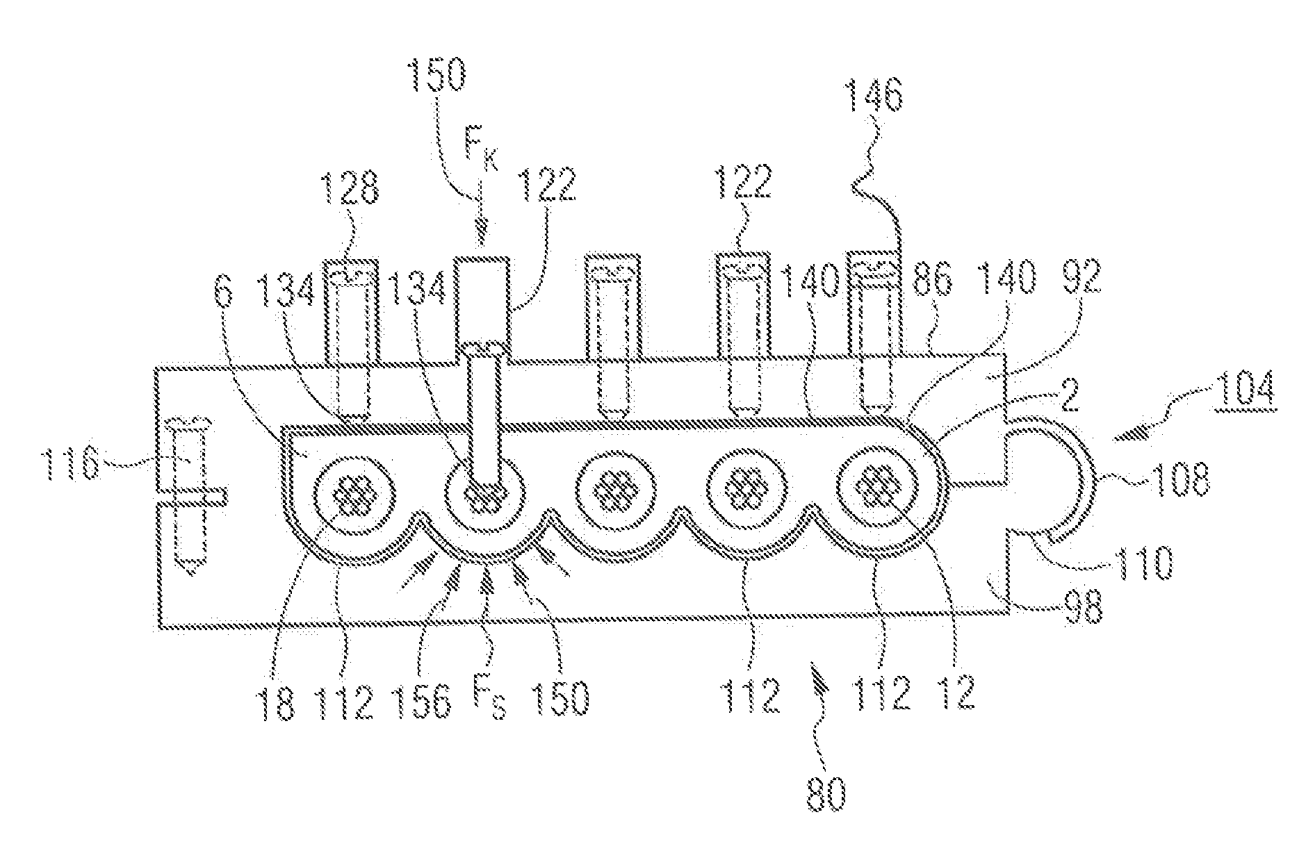
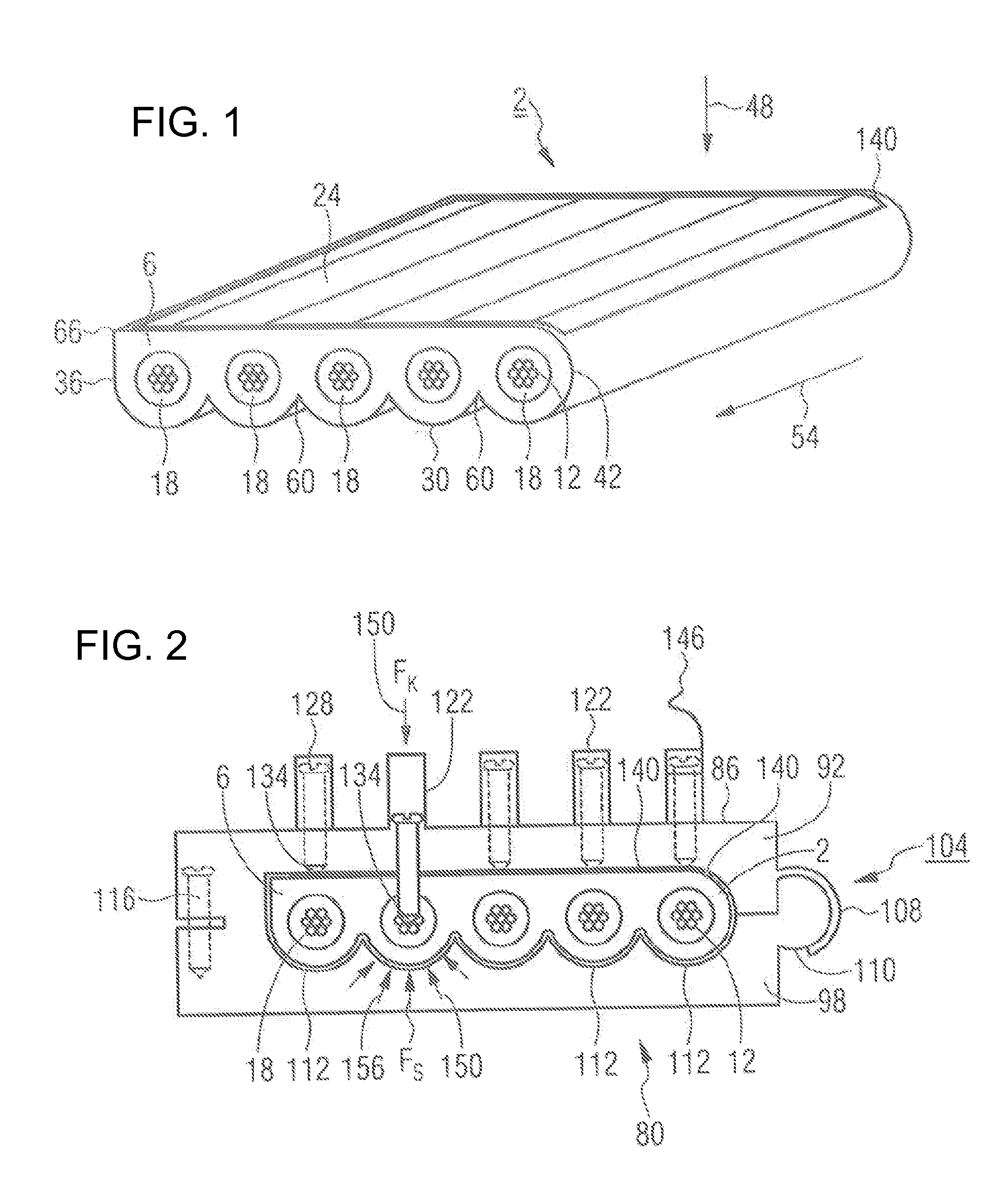
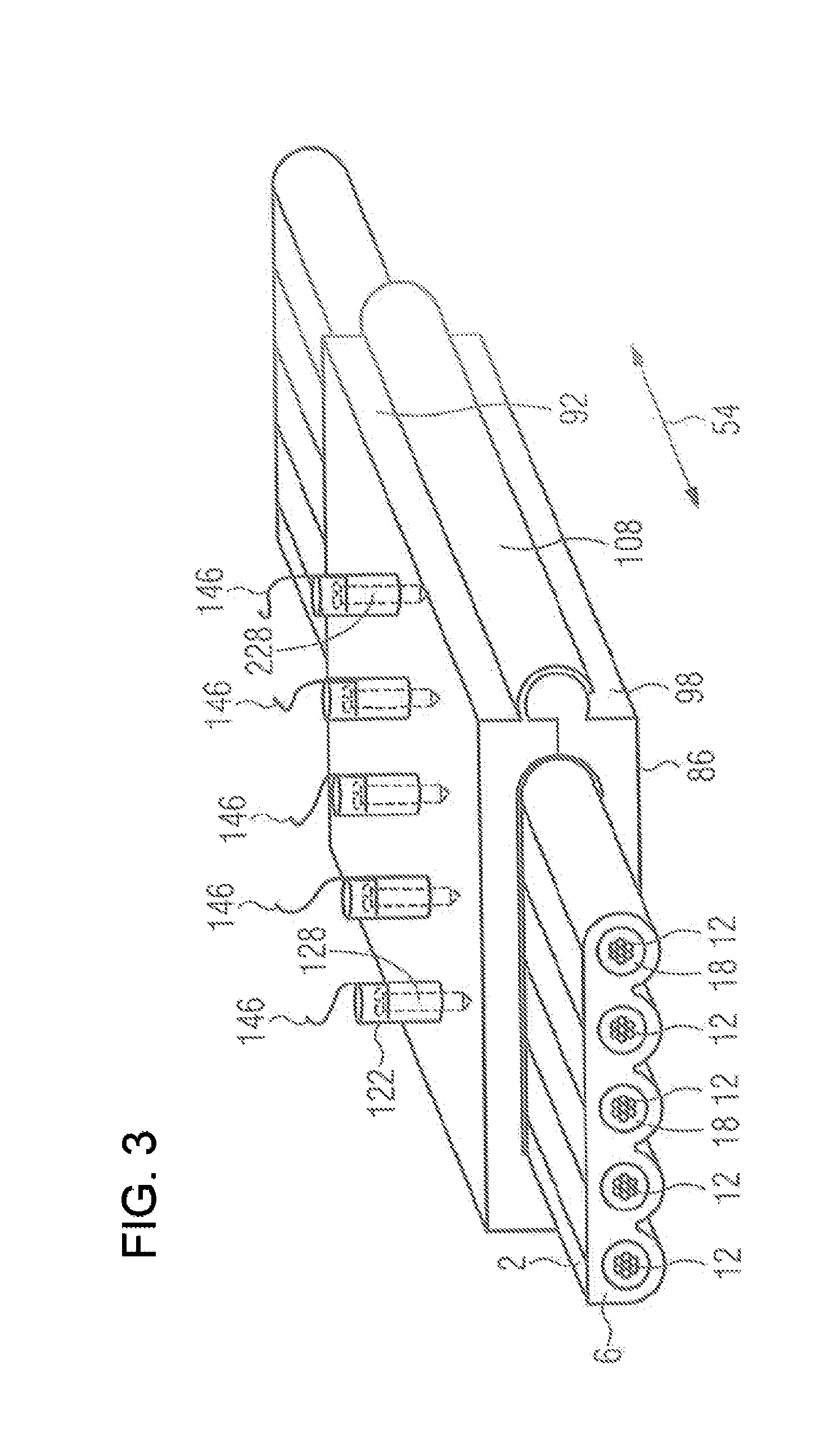
[0026]Referring now in detail to the figures of the drawings, in which identical parts are provided with the same reference symbols, and first, particularly, to FIG. 1 thereof, there is seen a flat ribbon cable 2 which has a sheath 6 or a sheathing in which five electrical cores 12 are disposed or embedded substantially in a common plane, wherein the cores 12 are each separately enclosed by an electrical insulation 18. The sheath 6 has a top sheath face 24 and a bottom sheath face 30 which are oriented substantially parallel to one another and parallel to the plane in which the cores 12 are disposed. The flat ribbon cable 2 also has two outer sheath faces 36, 42 which are each situated at the boundary regions of the flat ribbon cable 2 between top sheath face 24 and bottom sheath face 30. The flat ribbon cable 2 is suitable, for example, for an insulation-piercing contact-making process in which contact elements for making contact with the cores 12 are each routed through sheath 6 a...


PUM


Abstract

An electrical contact-making system includes a flat ribbon cable with a sheath which has a planar top sheath face, a core plane containing electrical cores and a bottom sheath face with constricted portions which are parallel to the cores and are each disposed between two of the cores. A tapping collar makes electrical contact with the cores. A peripheral sealing strip encloses a rectangular contact-making region and is disposed on a bottom face of the top part of the tapping collar facing the top sheath face of the flat ribbon cable.

Description

CROSS-REFERENCE TO RELATED APPLICATION[0001]This application claims the priority, under 35 U.S.C. §119, of German Patent Application DE 10 2013 002 740.3, filed Feb. 19, 2013; the prior application is herewith incorporated by reference in its entirety.BACKGROUND OF THE INVENTIONField of the Invention[0002]The present invention relates to an electrical contact-making system.[0003]Such a contact-making system is known, for example, from German Patent Application DE 10 2006 039 604 A1, corresponding to U.S. Pat. No. 7,667,140 B2. In that known contact-making system, contact is made with a flat ribbon cable, which has grooves on both sides, with the aid of piercing contacts in accordance with the insulation-piercing method. To that end, the piercing contacts are fastened to the cover of a multipartite housing. The housing is aligned with special markings on the grooved cable and then closed.SUMMARY OF THE INVENTION[0004]It is accordingly an object of the invention to provide an electric...

Claims


Application Information

Patent Timeline
Patent Type & Authority Applications(United States)
IPC IPC(8): H01R4/24
CPCH01R4/2404H01B7/0823H01R12/67H01R13/5205
Inventor BRAUN, MEINRADMUELLER, THOMAS
Owner WIELAND ELECTRIC
Why Eureka
Try Eureka