Heat performance test system

A technology for testing system and thermal performance, which is applied in the testing of machines/structural components, measuring devices, instruments, etc.

Active Publication Date: 2018-11-30
INST OF ENGINEERING THERMOPHYSICS - CHINESE ACAD OF SCI
View PDF9 Cites 7 Cited by
  • Summary
  • Abstract
  • Description
  • Claims
  • Application Information

AI Technical Summary

Problems solved by technology

Therefore, it is necessary to evaluate the performance of the heat exchanger. However, there is no high-temperature heat storage measurement platform with a po

Method used


Image

  • Heat performance test system
  • Heat performance test system
  • Heat performance test system

Examples


Embodiment 1

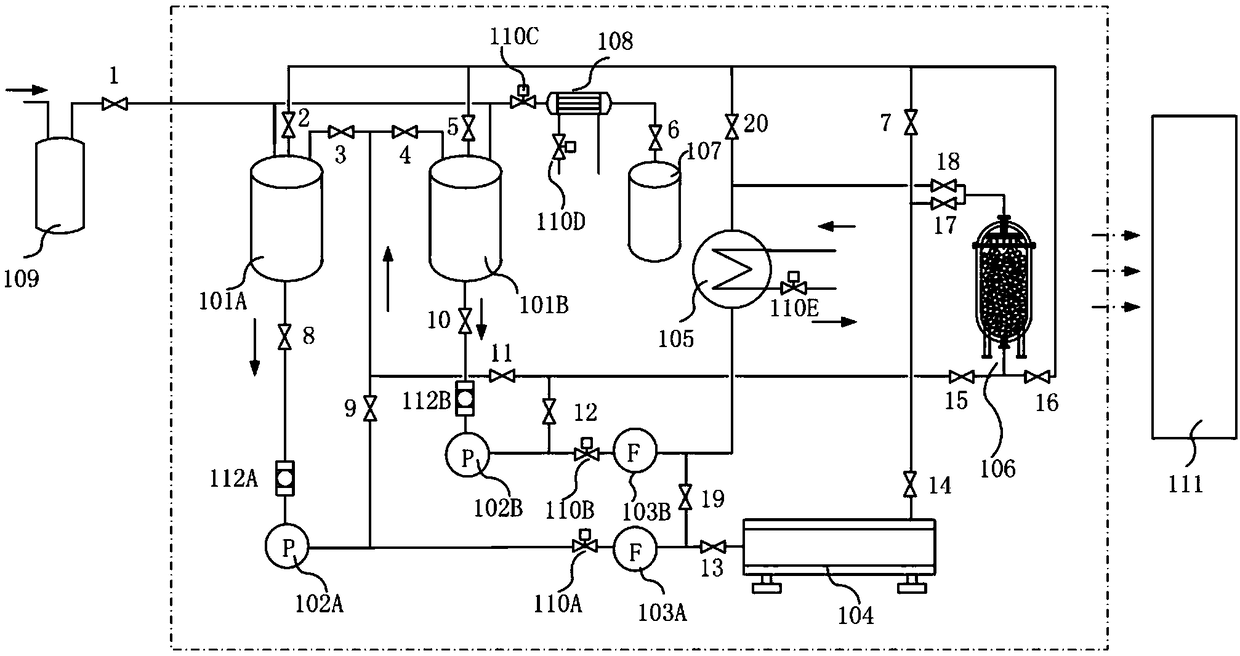
[0056] like figure 1 Shown is Embodiment 1 of the thermal performance testing system of the present invention. This embodiment is mainly used to test the heat storage performance of the heat storage device. This system includes a measurement and control unit 111, a heat generation and storage unit, a voltage stabilization unit, and a waiting Measure heat storage device 106.

[0057] Thermal energy generation and storage unit, including high temperature storage tank 101A, low temperature storage tank 101B, filters 112A, 112B, pumps 102A, 102B, electric heater 104, cooler 105, flow control components (including flow meters 103A, 103B, flow control valves 110A, 110B). Among them, valves 2, 3, and 8 are respectively provided at the first liquid inlet, the second liquid inlet, and the bottom liquid outlet of the top of the high-temperature storage tank 101A; the first liquid inlet at the top of the low-temperature storage tank 101B Valves 5, 4, 10 are respectively provided at the...

Embodiment 2

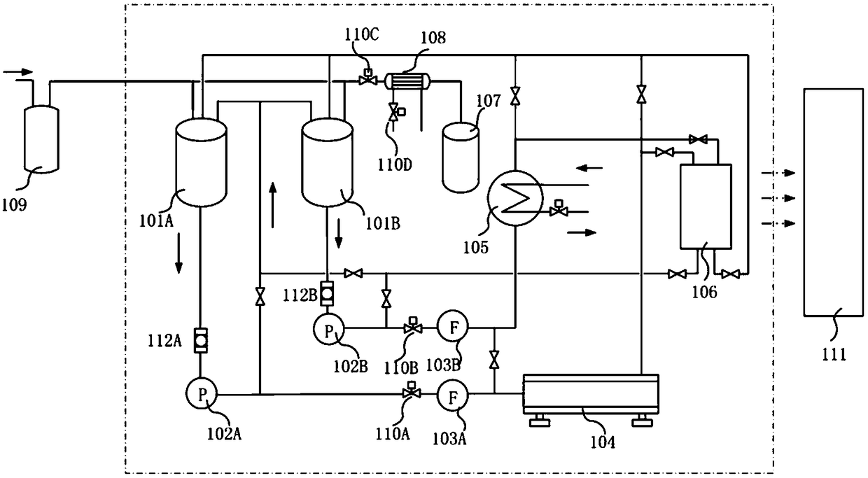
[0070] like figure 2 As shown, the difference from Example 1 is that this example is mainly used to test the heat exchange performance of the heat exchange device. The liquid discharge port of the heat exchange device 106 to be tested is connected to a high-temperature liquid discharge line and a low-temperature liquid discharge line, and both the high-temperature liquid discharge line and the low-temperature liquid discharge line are connected to the liquid inlets of the high-temperature storage tank 101A and the low-temperature storage tank 101B; When testing the heat exchange performance of the heat exchange device 106 to be tested, the low-temperature heat transfer fluid in the cryogenic storage tank 101B flows into the cold side of the heat exchange device 106 to be tested through the cooler 105 through the low-temperature liquid inlet pipeline driven by the cryopump 102B, And flow out into the low-temperature storage tank 101B through the high-temperature drain line of ...

Embodiment 3

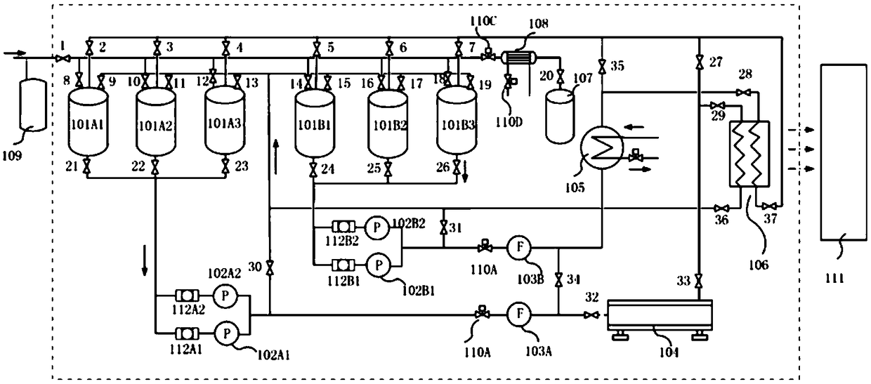
[0072] like image 3 Shown is Embodiment 3 of the high-temperature heat storage performance testing system of the present invention. This system is mainly composed of four parts: measurement and control unit 111, thermal energy generation and storage unit, pressure maintenance unit, and heat exchanger 106 of the device under test test system. The thermal energy generation and storage unit includes three parallel high-temperature storage tanks 101A1, 101A2, 101A3, three parallel low-temperature storage tanks 101B1, 101B2, 101B3, four filters 112A1, 112A2, 112B1, 112B2, four pumps 102A1, 102A2, 102B1, 102B2, one electric heater 104, one cooler 105, two high-temperature resistant flowmeters 103A, 103B; the pressure maintenance unit includes a buffer tank 109, a condenser 108, and a liquid collection tank 107; the device under test is the liquid / liquid heat exchanger 106 . The main working principle of the packed bed 106 is to complete energy exchange between two different liquid...


PUM


Abstract

The invention discloses a heat performance test system, which can perform test experiment and performance estimation on the heat storage/release performance of a heat storage device with high power and a wide temperature range and the heat exchange performance of a large-sized heat exchanger. The system consists of a test and control system, a heat energy production and storage system, a pressurestabilizing system, a tested device assembly, a pump valve assembly and the like, and can implement a test under a relatively wide temperature and pressure range. The system can also simulate outputting of unstable heat energy such as regenerable energy and implement a performance test and an operation strategy research on a large-scale medium and high-temperature heat storage device array, and can meet work such as a research and development test on key components of a compressed air energy storage system.

Description

technical field [0001] The invention belongs to the field of heat storage or heat transfer performance testing, and relates to a thermal performance testing system, which can test the heat storage / release performance of a high-power, wide-temperature range heat storage device and the heat transfer performance of a large heat exchanger. performance evaluation. The system can also simulate unsteady thermal energy output such as renewable energy, realize large-scale medium and high temperature heat storage device array performance testing and operation strategy research, and can meet the development and testing of key components of compressed air energy storage systems. Background technique [0002] Solar thermal power generation is a solar power generation technology with great development potential. The solar collector converts the collected solar radiation energy into superheated steam through a heat exchanger, and uses the traditional power cycle to generate electric energy...

Claims


Application Information

Patent Timeline
IPC IPC(8): G01M99/00
CPCG01M99/002Y02E60/14
Inventor 谢宁宁王亮陈海生王艺斐林曦鹏林霖
Owner INST OF ENGINEERING THERMOPHYSICS - CHINESE ACAD OF SCI
Why Eureka
Try Eureka