Device to block emesis and reflux and associated system and method

a technology of emesis and reflux and a device, applied in the field of medical devices, can solve problems such as interference with the gastric valve and the lower esophageal sphincter, and achieve the effect of preventing the device from adhesion

Active Publication Date: 2014-08-21
PNEUMOFLEX SYST
View PDF15 Cites 25 Cited by
  • Summary
  • Abstract
  • Description
  • Claims
  • Application Information

AI Technical Summary

Benefits of technology

[0009]In another example, at least one pressure sensor is located on the device body and configured to measure pressure in at least one of the upper esophagus, lower esophagus, and stomach. This at least one pressure sensor is formed a pressure transducer and a transducer lead connecting the pressure transducer. In another example, at least one pH sensor is carried by the device body. In another example, the esophageal cuff is radio-opaque to aid in placement of the esophageal cuff at a predetermined location within the esophagus. In another example, a suction lumen is formed within the device body and suction ports communicate with the suction lumen and are configured to permit suction within the esophagus. The suction ports may be configured as one-way valves to permit suction for emesis and / or reflux into the suction lumen when a vacuum is drawn therethrough. A sump port may be positioned at the distal end and a sump lumen formed the length of the device body and configured for venting gas and preventing adherence of the device against the gastric wall. A nebulizer lumen may extend along the device body and comprise a port through which medication is delivered for administrating an involuntary reflex cough test. The esophageal cuff protects the airway during the involuntary reflex cough test.

Problems solved by technology

This procedure is sometimes a limited analysis that is not always accurate to determine whether there is a reflux problem, and thus, requiring an Ng / Og device, which in some cases can interfere with the gastric valve and the lower esophageal sphincter.

Method used


Image

  • Device to block emesis and reflux and associated system and method
  • Device to block emesis and reflux and associated system and method
  • Device to block emesis and reflux and associated system and method

Examples


Embodiment Construction

[0048]Different embodiments will now be described more fully hereinafter with reference to the accompanying drawings, in which preferred embodiments are shown. Many different forms can be set forth and described embodiments should not be construed as limited to the embodiments set forth herein. Rather, these embodiments are provided so that this disclosure will be thorough and complete, and will fully convey the scope to those skilled in the art.

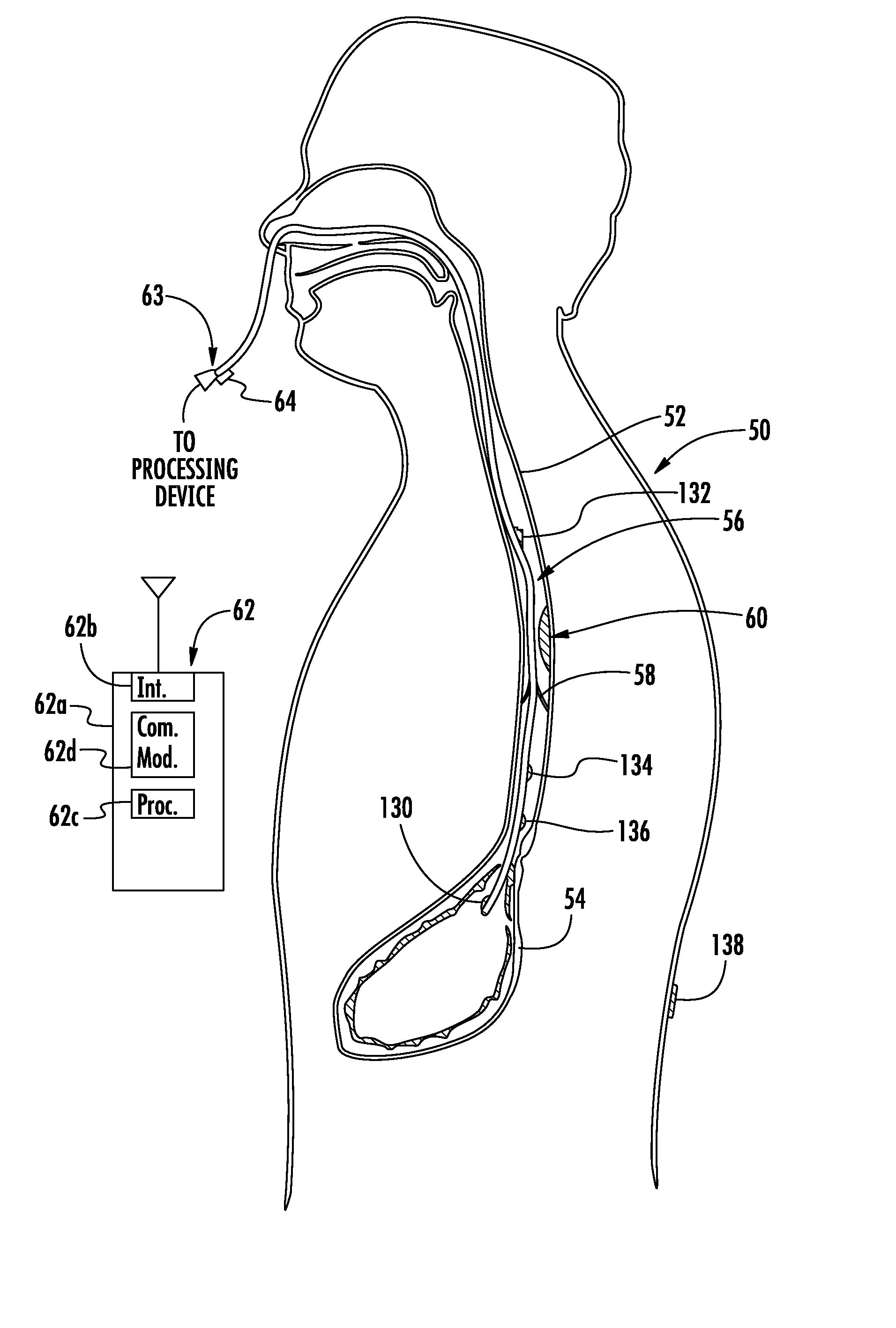
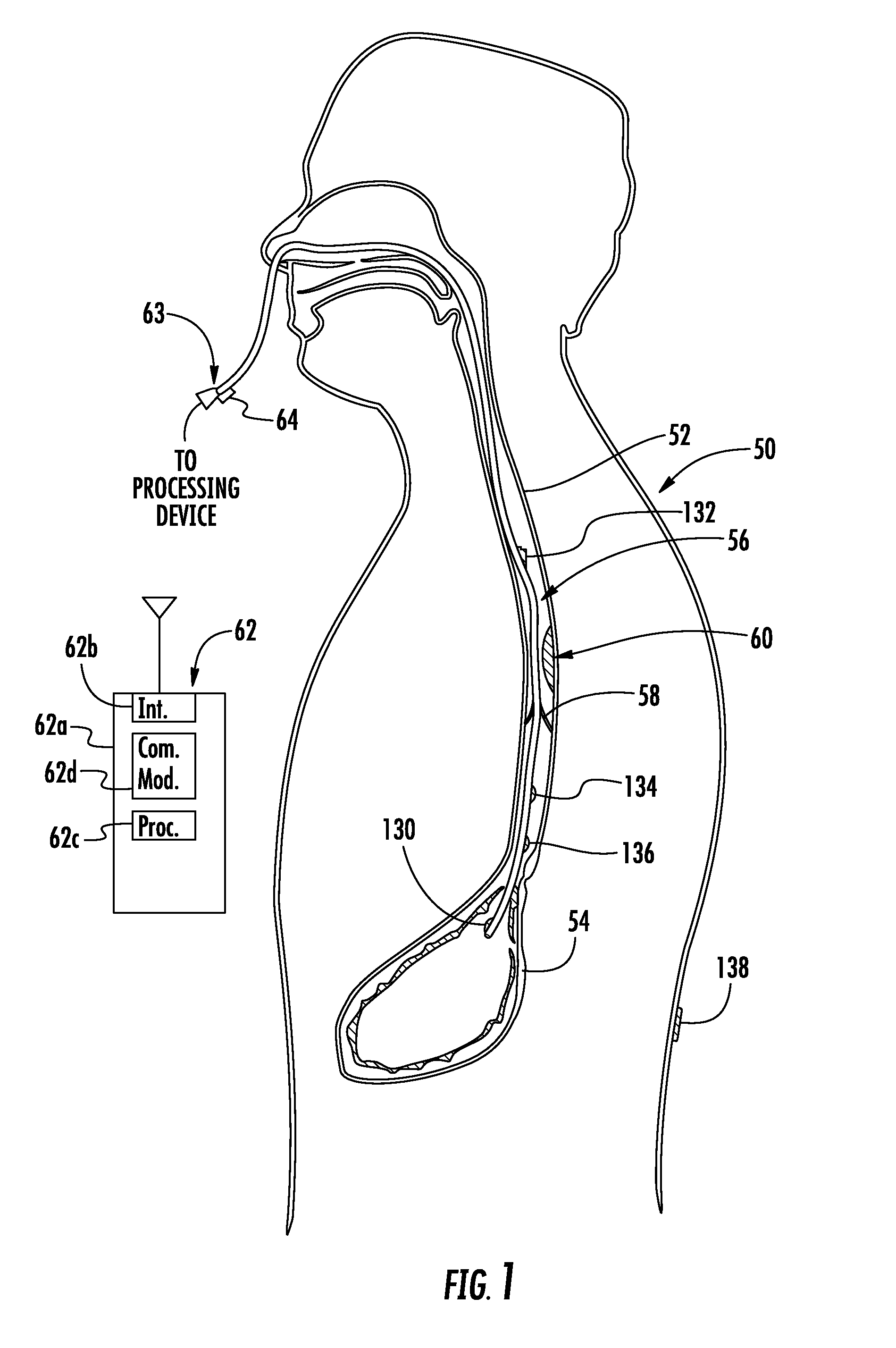
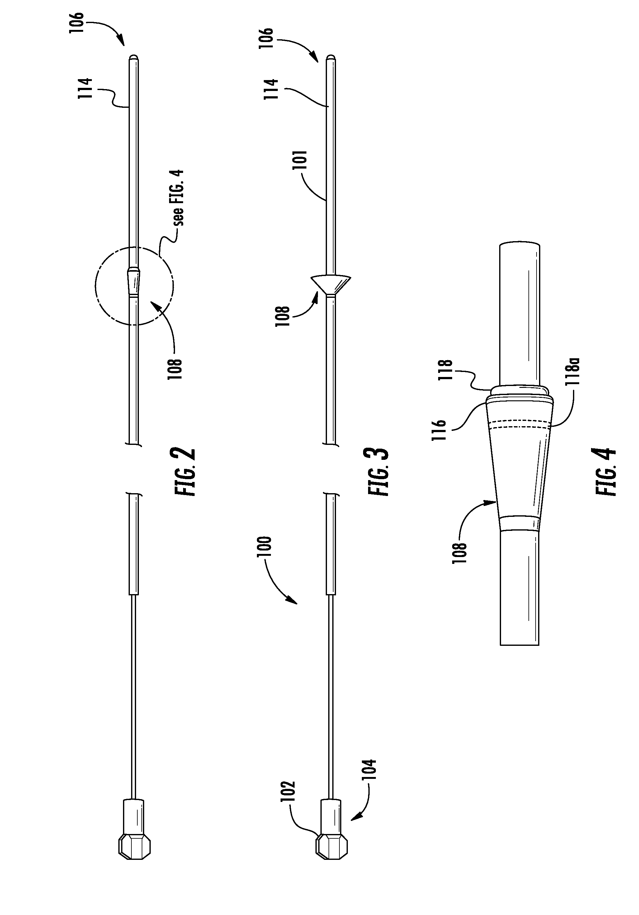
[0049]As will be described in detail below, FIGS. 2-18 illustrate a passive emesis containment system formed in this example as a nasogastric (Ng) tube having a passive valve and FIGS. 19-27 illustrate an active emesis containment system as a nasogastric (Ng) tube that includes an active valve having an inflatable balloon or other member that actively opens the valve. It should be understood that the tubes could be formed as many different types of nasogastric / osogastric (Ng / Og) tubes depending on the design requirements of those skilled in ...


PUM


Abstract

A nasogastric / orogastric (Ng / Og) device includes a main lumen configured for at least one of gastric decompression, enteral feeding and enteral medication administration. An expandable esophageal cuff is carried by the device body and configured in a normally expanded position such that when inserted within the esophagus, the esophageal cuff conforms to the interior surface of the esophagus and emesis and / or reflux is blocked from passing out of the stomach and past the esophageal cuff. A vacuum lumen is carried by the device body and connected to the expandable esophageal cuff. When vacuum is applied, the esophageal cuff is contracted against the device body to permit the device to be inserted and placed within the esophagus. When the vacuum is released, the esophageal cuff expands against the interior surface of the esophagus.

Description

RELATED APPLICATION(S)[0001]This application is a continuation-in-part application of patent application Ser. No. 13 / 767,922, filed Feb. 15, 2013, the disclosure of which is hereby incorporated by reference in its entirety.FIELD OF THE INVENTION[0002]This invention is related to the field of medical devices, and more particularly, this invention is related to a device for blocking emesis and / or reflux and a system of diagnosing a physiological abnormality in a patient by inducing an involuntary reflex cough test (iRCT).BACKGROUND OF THE INVENTION[0003]Commonly assigned U.S. application Ser. No. 13 / 354,100 filed Jan. 19, 2012 by the same inventors, the disclosure which is hereby incorporated by reference in its entirety, discloses a system and method of diagnosing acid reflux using an involuntary reflex cough test. In one example as disclosed, a nasogastric / orogastric (Ng / Og) device is inserted though the mouth or nose and through the esophagus and into the stomach and the involuntar...

Claims


Application Information

Patent Timeline
Patent Type & Authority Applications(United States)
IPC IPC(8): A61J15/00A61B5/00A61B5/145A61M1/00A61M25/01A61B5/0488A61B5/04A61B5/03A61B6/12G16H20/13G16H20/40G16H50/20
CPCA61J15/0049A61B5/037A61B5/6853A61B5/14539A61M1/0088A61M25/0108A61B5/4884A61B5/0488A61B5/04012A61B6/12A61J15/0046A61B5/4211A61M25/0029A61M25/1018A61M2025/0002A61M2025/1052A61M2025/1079A61B5/1107A61B5/687A61J15/0003A61J15/0073A61J15/0088G16H50/20G16H20/13G16H20/40A61B5/316A61B5/389A61B5/7282A61M1/90A61B2017/00827
Inventor ADDINGTON, W. ROBERTMILLER, STUART P.
Owner PNEUMOFLEX SYST
Why Eureka
Try Eureka