Method of using virtual gantries to optimize the charging performance of in-vehicle parking systems

a charging system and virtual gantry technology, applied in the field of vehicle charging methods and systems, to achieve the effect of improving charging performan

Inactive Publication Date: 2014-08-21
APPLIED TELEMETRICS
View PDF3 Cites 35 Cited by
  • Summary
  • Abstract
  • Description
  • Claims
  • Application Information

AI Technical Summary

Benefits of technology

[0017]The present method and system are directed to determining geographic location of a vehicle to enable an in-vehicle parking meter. The method and system aim to improve charging performance by addressing certain wireless positioning errors which may occur for any positioning technology such as GNSS, Cell-tower or WiFi or equivalent, particularly within urban environments or other forms of harsh signal terrain that is antithetical to reliable location determination using radio technologies.

Problems solved by technology

For drivers, making payments for the use of a parking space is often a time consuming nuisance and inefficient process—i.e., a high transaction cost for the motorist is due to frustrating, confusing, annoying, and time-wasting activities to find a parking spot and then to make a modest payment, while possibly misinterpreting rules, facing uncertainty regarding the amount to pay or duration of permitted stay, including potential difficulty or error in returning on time and the associated risk of incurring a parking citation for an expired or incorrect payment.
For parking operators, the management of parking payments is expensive, difficult to optimize, and often incurs lost opportunities for both private-sector profit and public-sector transportation demand management:1. Collecting payments for use of a parking space is often an expensive and inefficient process—i.e., the transaction cost of collecting parking payments is high and the machine and human-labor processes involved are wasteful and sometimes contentious.
There are many reasons for this: the expense of curbside payment equipment and its maintenance, gating systems, manual collection, enforcement, accounting systems and many other operational components in aggregate can consume half or more of the parking fees collected, especially in the case of street parking.
The parking operator generally invests in payment collection systems and costly enforcement methods that treat all customers as liable to cheat, which tends to increase equipment and enforcement expense.2. Setting optimal prices whether for revenue maximization or transportation demand management is complicated due to one of more of lack of information, lack of ability to respond to local demand in a timely manner, and lack of efficient and easily understood methods to inform motorists of variable payment requirements.3. Access to user loyalty methods and processes is generally restricted to methods for motorists who happen to live, work or go to school in a location at or near a particular parking lot.
This implies three lost opportunities:a. Creating loyalty among drivers who could choose to park frequently in a particular facility, but not sufficiently often to purchase a monthly parking pass.b. There are currently few or no effective ways to offer a form of multi-site access account for purposes of customer retention or customer attraction for a parking operator who manages more than one parking location (lot or garage).c. There are no reliable systems to offer multi-operator service and loyalty schemes for parking operators as there are for airline operators as are managed by airline “code-share” schemes.4. There are lost opportunities reflected in the diminished access to broad consumer marketing systems that incorporate location-based marketing schemes such as coupons or discounts.
This represents a loss for parking payment system operators as well as their parking customers and business neighbors.
Hence, current parking operations are expensive, inefficient, complex and rife with lost opportunities.
Unfortunately, wireless positioning errors ranging up to a few tens of meters are common in telemetry systems.
This can lead to positioning uncertainty resulting in mischarging for parking.

Method used


Image

  • Method of using virtual gantries to optimize the charging performance of in-vehicle parking systems
  • Method of using virtual gantries to optimize the charging performance of in-vehicle parking systems
  • Method of using virtual gantries to optimize the charging performance of in-vehicle parking systems

Examples


Embodiment Construction

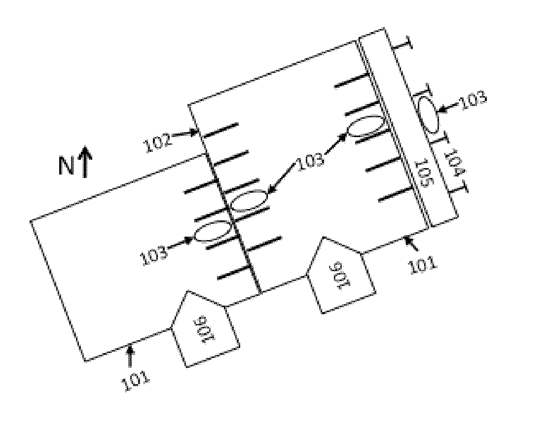
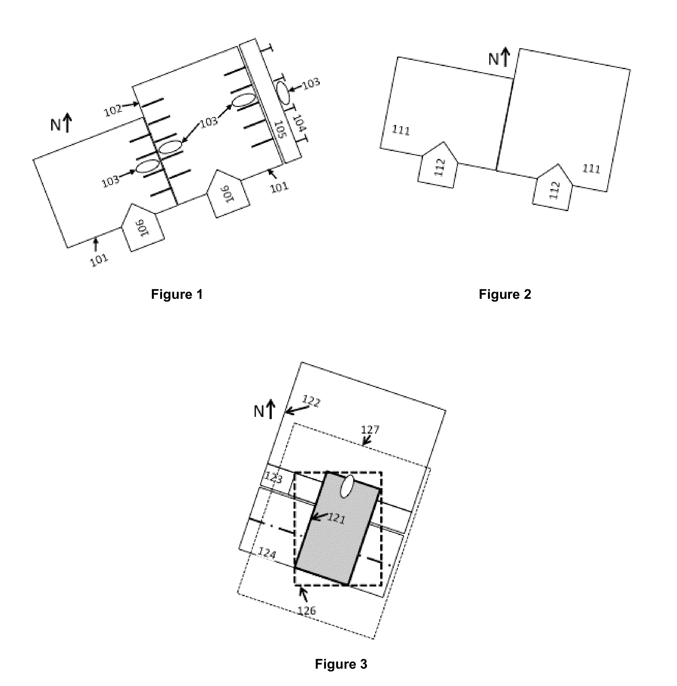
[0068]In the case of GNSS, tall buildings and other earth-surface features can cause signal reflections, radio-shadows and in the particular case of parking garages, the number of satellites in view (NSV) may decline to a very small number, possibly zero, depending on receiver technology, implying loss of positioning in the absence of additional techniques. As FIGS. 1 and 2 illustrate, there are several ways that these errors can result in mischarging for parking. As shown in FIG. 1, it is possible for two surface lots 101 to share a boundary 102 such that vehicles 103 parking in one lot could be mistakenly identified by a wireless location system as parking in the other one. Similarly, a surface lot 101 might be positioned adjacent to a block-face of street parking spots 104, where adjacent might mean separated only by a sidewalk 105 of 1.5 to two meters in width in an environment where 5 m or 10 m positioning errors are common. This can contribute to an erroneous billing assignmen...


PUM


Abstract

A method is provided for charging a user for parking a vehicle in a chargeable parking facility. Signals are received from at least one signal source at a receiver disposed within the vehicle. Using the received signals, an approximate path of travel of the vehicle is identified and it is determined whether the vehicle's approximate path of travel crosses a geofence associated with at least one boundary region of the chargeable parking facility. If the vehicle's approximate path of travel crosses the geofence, it is determined, with a degree of certainty, whether a park point approximating a location where the vehicle has come to rest lies inside the chargeable parking facility. If the park point is determined to lie inside the chargeable parking facility, the park point is associated with a charge, and the charge is assessed to the user.

Description

CROSS-REFERENCE TO RELATED APPLICATIONS[0001]This application claims benefit of U.S. provisional patent application Ser. No. 61 / 767,425, filed Feb. 21, 2013, which is herein incorporated by reference.BACKGROUND OF THE INVENTION[0002]1. Field of the Invention[0003]The invention relates to charging methods and systems for vehicle parking.[0004]2. Description of the Related Art[0005]For drivers, making payments for the use of a parking space is often a time consuming nuisance and inefficient process—i.e., a high transaction cost for the motorist is due to frustrating, confusing, annoying, and time-wasting activities to find a parking spot and then to make a modest payment, while possibly misinterpreting rules, facing uncertainty regarding the amount to pay or duration of permitted stay, including potential difficulty or error in returning on time and the associated risk of incurring a parking citation for an expired or incorrect payment. Drivers are faced with a large number of payment...

Claims


Application Information

Patent Timeline
Patent Type & Authority Applications(United States)
IPC IPC(8): G07B15/00G06Q20/32
CPCG06Q20/3224G07B15/00G07B15/02
Inventor GRUSH, BERNARDSAURIOL, BRUNOLEBLANC, JOSEPH
Owner APPLIED TELEMETRICS
Why Eureka
Try Eureka