
Method for obtaining edge prep profiles of cutting tools

a technology of edge prep and cutting tool, which is applied in the direction of manufacturing tools, instruments, and using mechanical means, can solve the problems of not having a good way of measuring the edge prep on cutting tools, complex cutting tools, and unmanageable honed edges over time,

Inactive Publication Date: 2014-08-28
GENERAL ELECTRIC CO
View PDF1 Cites 3 Cited by
  • Summary
  • Abstract
  • Description
  • Claims
  • Application Information

AI Technical Summary

Benefits of technology

The invention provides an automatic way to measure the edge prep on a cutting tool with a point sensor. The method involves scanning the edge points of the tool and repositioning the sensor to focus on the target edge point. Then, the region of interest containing the target edge point is scanned to gather information for edge profile analysis. This allows for precise measurement of the edge prep on the tool, which can help improve the efficiency and accuracy of the cutting process.

Problems solved by technology

Many cutting tool manufacturers established various edge prepping processes to get desired cutting edges, for different applications, though they did not have a good way of measuring the edge preps on cutting tools, specifically, complex cutting tools.
Moreover, in some cases, when users could not get satisfactory performance from purchased cutting tools, they may hone in-coming cutting tools by themselves.
These honed edges over time might become unmanageable.
However, some machined parts are very sensitive to the edge preps of the cutting tools.
For example, airfoil thickness may be very sensitive to improper edge prep treatment.
A cutting edge with a too heavy hone may cause oversize conditions on the airfoil, due to deflection, resulting in additional, and costly, benching or rework.
One with an edge prep that is too light, or with no edge prep at all, could result in undersize conditions, excessive chatter, broken cutters, and possibly even scrap hardware.
Usually this manual positioning process is tedious and time consuming, and very dependent upon operator skill to obtain good quality data due to the very limited range of angles and measurement range of these methods.

Method used


Image

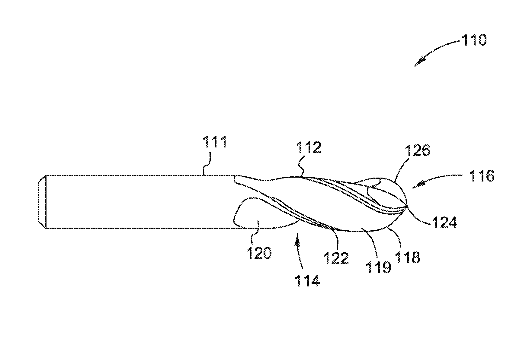
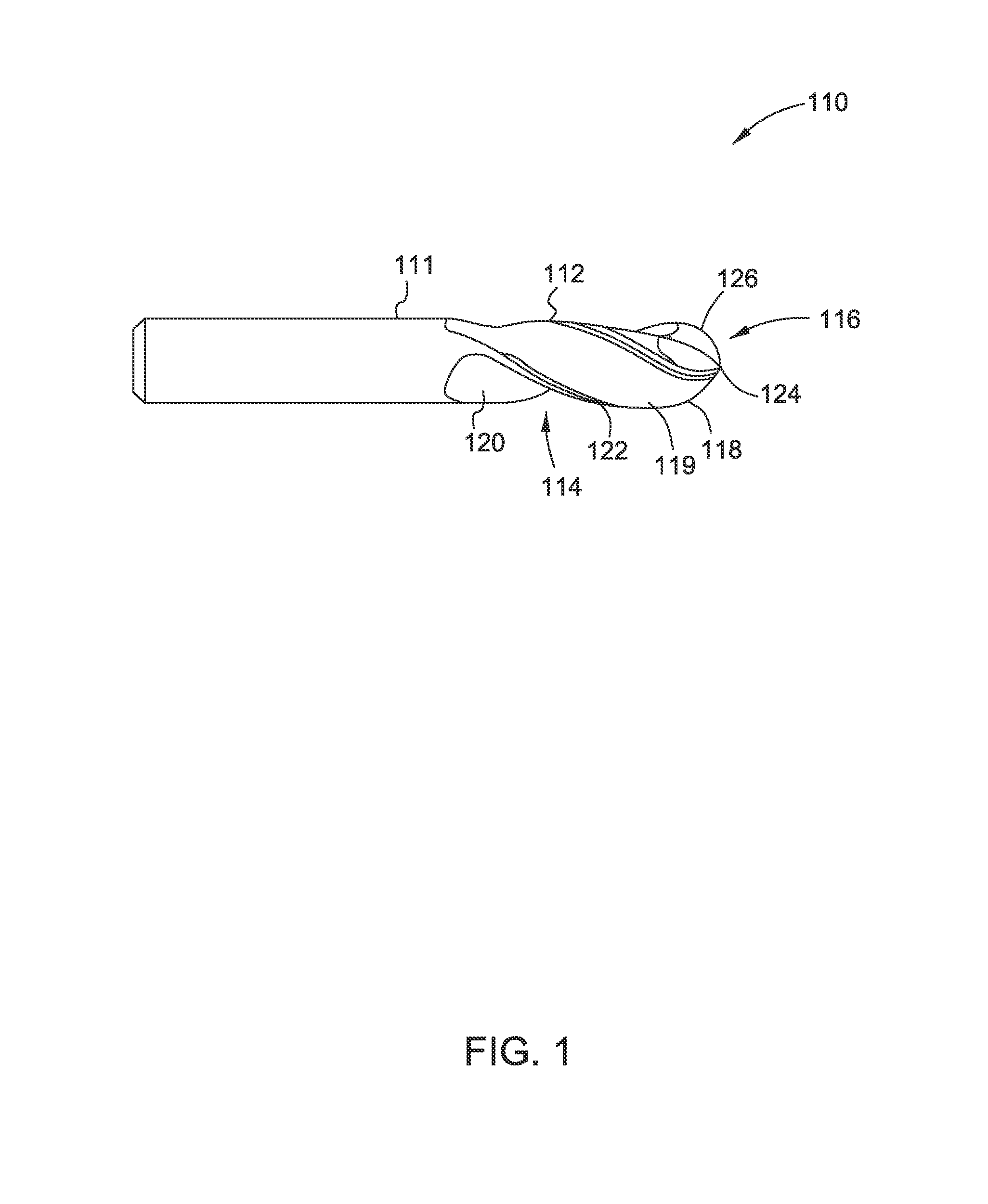
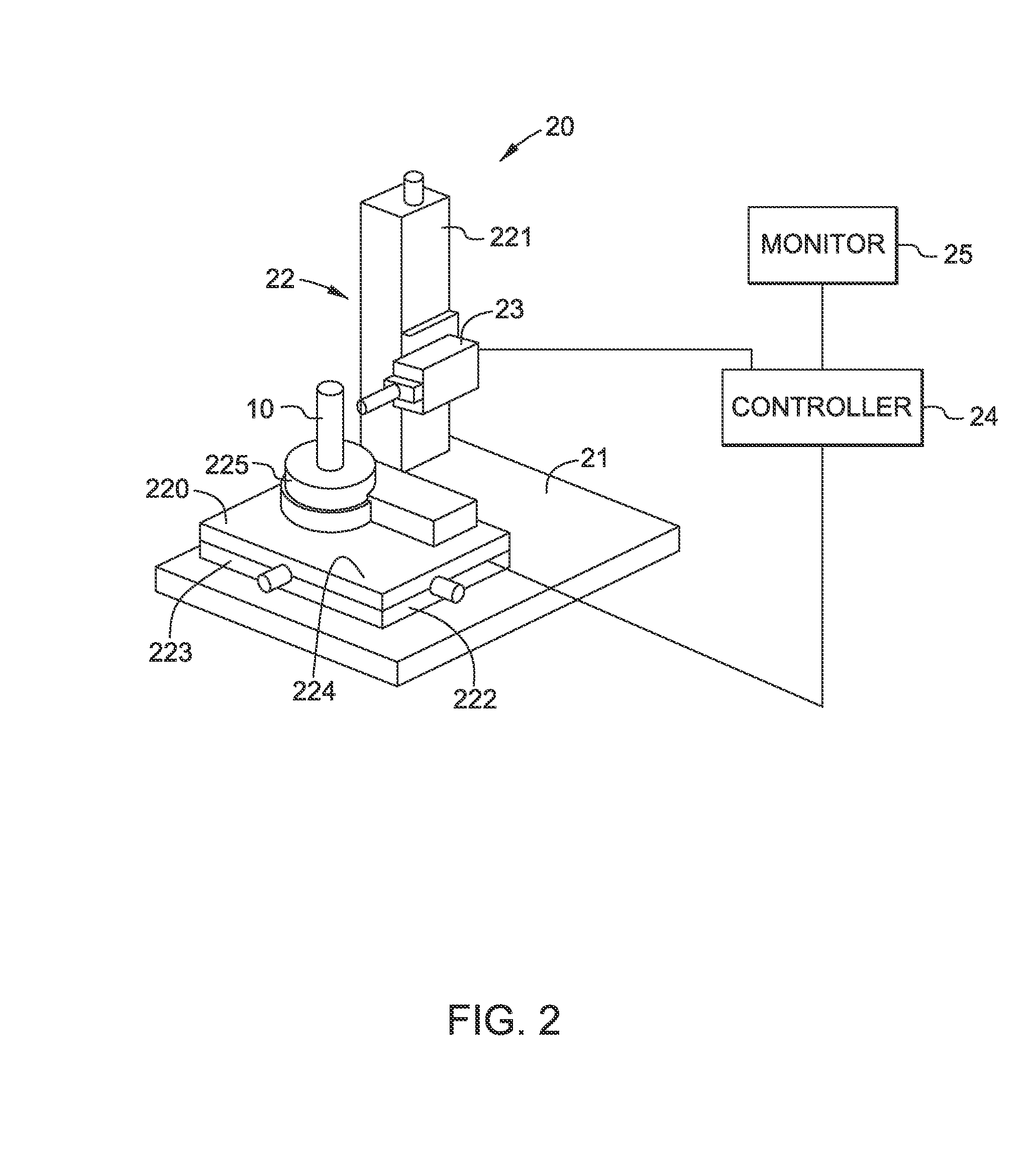
  • Method for obtaining edge prep profiles of cutting tools
  • Method for obtaining edge prep profiles of cutting tools
  • Method for obtaining edge prep profiles of cutting tools

Examples


Embodiment Construction

[0021]Embodiments of the present disclosure will be described herein below with reference to the accompanying drawings. In the subsequent description, well-known functions or constructions are not described in detail to avoid obscuring the disclosure in unnecessary detail.

[0022]Approximating language, as used herein throughout the specification and claims, may be applied to modify any quantitative representation that could permissibly vary without resulting in a change in the basic function to which it is related. Accordingly, a value modified by a term or terms, such as “about” or “substantially”, is not to be limited to the precise value specified. In some instances, the approximating language may correspond to the precision of an instrument for measuring the value.

[0023]Any numerical values recited herein include all values from the lower value to the upper value in increments of one unit provided that there is a separation of at least 2 units between any lower value and any high...


PUM


Abstract

A method for obtaining an edge prep profile of a cutting tool with a point sensor. The method includes: (a) scanning edge points of the cutting tool, including a target edge point on a target edge, with the point sensor, by rotating the cutting tool around its axis, to generate a first point cloud; (b) repositioning the point sensor and cutting tool relative to each other based on the location and orientation information of the target edge point, such that the sensor focus is at a region of interest containing the target edge point; and (c) scanning the region of interest using the point sensor to generate a second point cloud. The first point cloud includes location and orientation information of the target edge point. The second point cloud includes information for edge profile analysis.

Description

FIELD OF THE INVENTION[0001]Embodiments of the present invention relate to methods for obtaining edge prep profiles of cutting tools. Embodiments of the present invention specifically relate to automated methods for obtaining edge prep profiles of cutting tools with a point sensor, from which edge prep profiles on cutting tools may be measured.BACKGROUND OF THE INVENTION[0002]Various types of cutting tools are known and are in use for machining parts. It is well-known that prepping (e.g., honing, chamfering) edges on high performance cutting tools increases tool life and enhances machined part quality, when applied correctly. Many cutting tool manufacturers established various edge prepping processes to get desired cutting edges, for different applications, though they did not have a good way of measuring the edge preps on cutting tools, specifically, complex cutting tools. Moreover, in some cases, when users could not get satisfactory performance from purchased cutting tools, they ...

Claims


Application Information

Patent Timeline
IPC IPC(8): G01B21/20
CPCB23Q17/0933G01B21/20G01B11/24B23Q17/0938
Inventor DU, XIAOMINGHARDING, KEVIN GEORGEWEAVER, HOWARD PAULBAIRD, JAMES ALLENMEYER, KEVIN WILLIAMGU, JIAJUN
Owner GENERAL ELECTRIC CO
Learn More