Working vehicle

a technology for working vehicles and transmission cases, applied in auxiliary drives, control devices, gearing, etc., can solve the problems of difficult arrangement of valves on the side surfaces of transmission cases, and achieve the effect of improving general versatility and improving manufacturing

Active Publication Date: 2014-08-28
ISEKI & CO LTD
View PDF8 Cites 7 Cited by
  • Summary
  • Abstract
  • Description
  • Claims
  • Application Information

AI Technical Summary

Benefits of technology

[0009]An object of the invention is to provide a working vehicle capable...

Problems solved by technology

Therefore, the oil passage formed in the transmission case is also formed at various front and rear positions of the transmission c...

Method used


Image

  • Working vehicle
  • Working vehicle
  • Working vehicle

Examples


Embodiment Construction

[0054]Hereinafter, an illustrative embodiment of the invention will be specifically described with reference to the drawings.

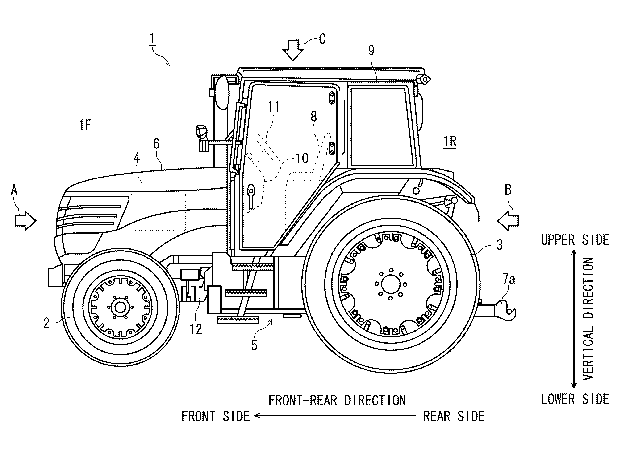
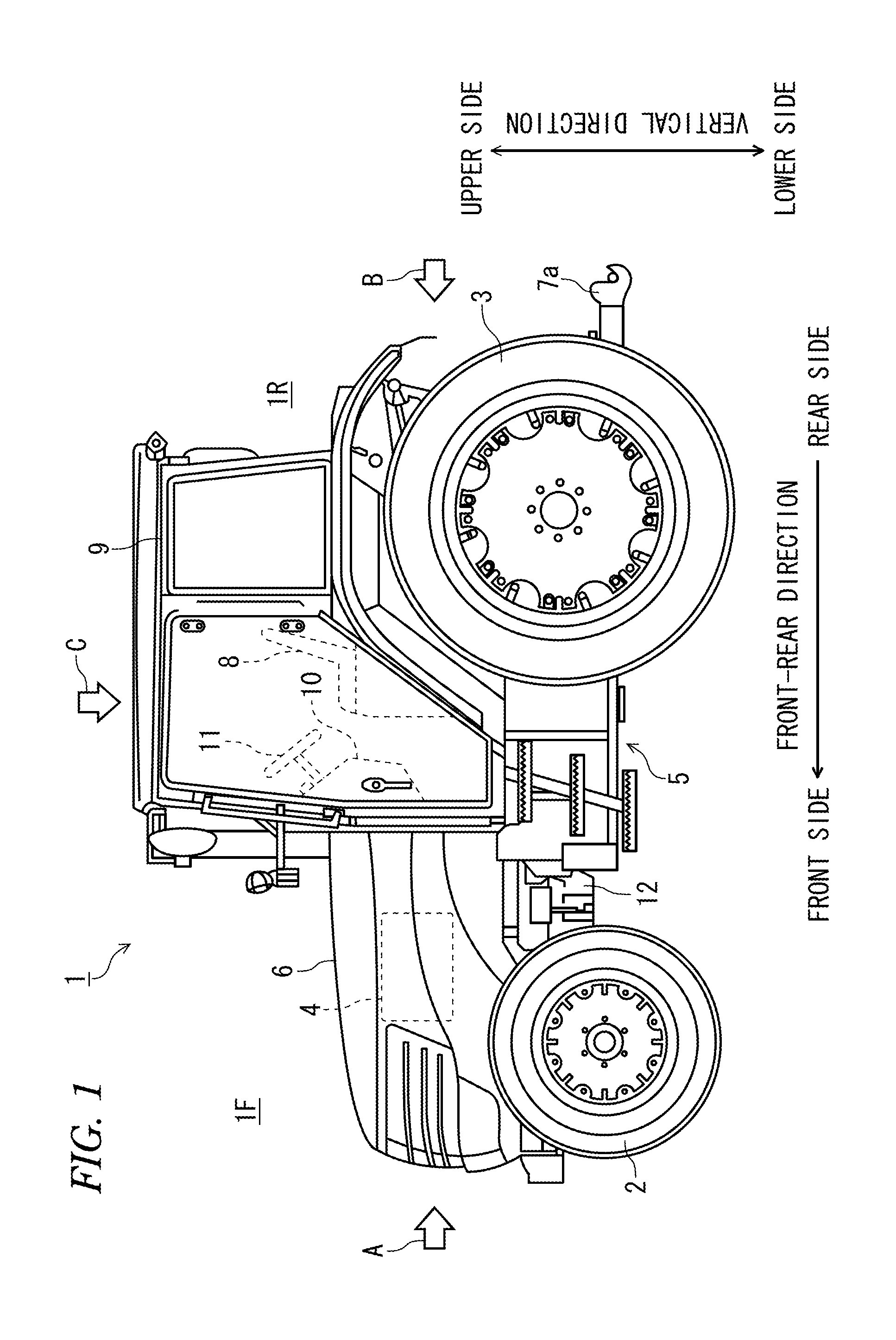
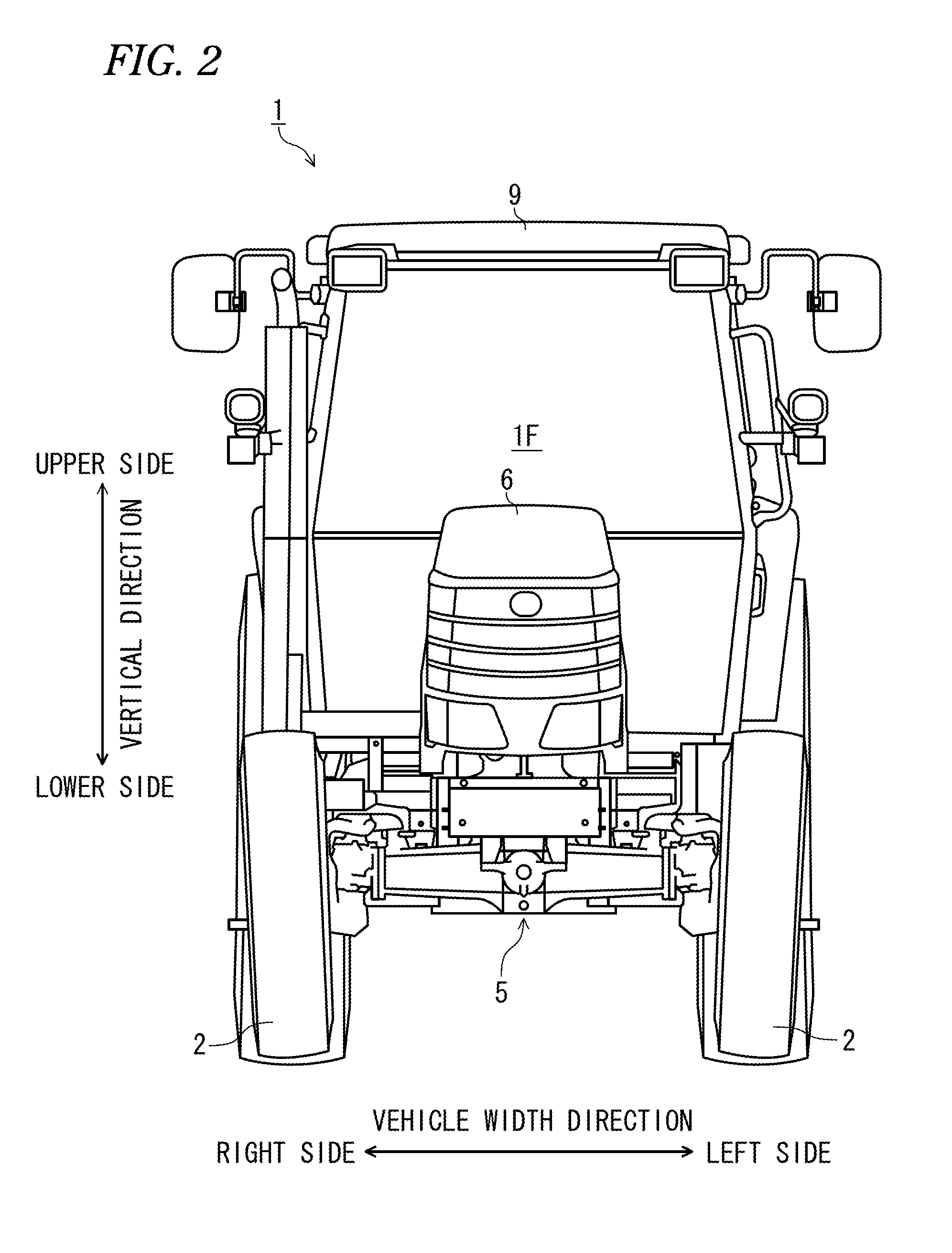
[0055]Meanwhile, in below descriptions, a front-rear direction is a front-rear direction of a tractor 1. Additionally, the front-rear direction is a traveling direction when the tractor 1 goes straight ahead, and a front side of the traveling direction is referred to as a front side in the front-rear direction and a rear side thereof is referred to as a rear side in the front-rear direction. The traveling direction of the tractor 1 is a direction that is directed from an operator seat 8 of the tractor 1 towards a steering wheel 11 when the tractor 1 travels in a straight line, and the steering wheel 11-side is the front side and the operator seat 8 is the rear side. Also, a vehicle width direction is a direction horizontally orthogonal to the front-rear direction. Here, at a state of seeing the front side of the front-rear direction, the right side is referred...


PUM


Abstract

According to one embodiment, a working vehicle includes: a transmission case including a front transmission case and a rear transmission case, and a power transmission mechanism, arranged in the transmission case, configured to transmit rotating power from an engine to rear wheels or front wheels and transmit the rotating power to an implement mounted to a vehicle body, including: an input shaft; a first switching mechanism configured to switch a rotation corresponding to the rotating power to rotation in advancing direction or reversing direction; a main change speed mechanism; an auxiliary change speed mechanism; a second switching mechanism configured to switch whether to transmit the rotating power to the front wheels or not; and a PTO driving mechanism, wherein a clutch of the first switching mechanism, a clutch of the second switching mechanism and a clutch of the PTO driving mechanism are arranged in the front transmission case.

Description

BACKGROUND[0001]1. Field of the Invention[0002]The invention relates to a working vehicle such as an agricultural tractor.[0003]2. Description of the Related Art[0004]Regarding a working vehicle of the related art, for example, JP-A-2004-196106 discloses a configuration of a hydraulic circuit of a power vehicle including an engine mounted on a vehicle body having front wheels and rear wheels, a transmission case, in which a transmission having driving mechanisms including a variety of clutches and gear mechanisms for speed-changing a rotational speed of the engine to appropriate rotational speeds of the front and rear wheels in accordance with a traveling state, is accommodated, and a hydraulic pump for supplying an operating oil to the various driving mechanisms, wherein a decompression valve, which introduces a high-pressure oil from the hydraulic pump through an external oil passage and divides and outputs the same into a specified pressure and a surplus pressure, is provided on ...

Claims


Application Information

Patent Timeline
IPC IPC(8): B60K17/28
CPCB60K17/28B60K17/04B60K17/34F16H2057/02056F16H2037/044F16H37/043
Inventor SAGAWA, NOBORU
Owner ISEKI & CO LTD
Why Eureka
Try Eureka