Supercharge Your Innovation With Domain-Expert AI Agents!

Simple low cost tip-tilt wavefront sensor having extended dynamic range

a wavefront sensor and dynamic range technology, applied in the field of free space optical (fso) communications, can solve the problems of aberration error, poor seeing conditions, degraded spatial resolution, etc., and achieve the effect of low cost and high reliability system

Active Publication Date: 2014-09-04
EOS DEFENSE SYST USA INC
View PDF29 Cites 4 Cited by
  • Summary
  • Abstract
  • Description
  • Claims
  • Application Information

AI Technical Summary

Benefits of technology

The patent describes a system that can correct aberrations in optical signals using a foreoptic assembly, a diffractive optical element, a wavefront sensor, and an active optical element. The system measures the aberration of the incoming optical signal and adjusts the active optical element to correct it. This results in a high-quality optical signal that is reliable and cost-effective. In another embodiment, the system automatically accounts for the aberration in the outgoing optical signal by transmitting it along the same optical path as the incoming optical signal.

Problems solved by technology

The effects of atmospheric seeing on an FSO signal presents an effective limiting aperture size of ro for an arriving wavefront, leading to degraded spatial resolution.
Under good seeing conditions, tip-tilt aberrations, corresponding to motion of the centroid of the FSO signal, are the major contributors to the aberration error.
Bad seeing conditions.
In bad seeing conditions, higher order aberration contribute significantly to the aberration error, and thus correcting for just the tip-tilt aberrations does not provide a significant improvement in obtainable resolution.

Method used


Image

  • Simple low cost tip-tilt wavefront sensor having extended dynamic range
  • Simple low cost tip-tilt wavefront sensor having extended dynamic range
  • Simple low cost tip-tilt wavefront sensor having extended dynamic range

Examples


Embodiment Construction

Overview and Benefits

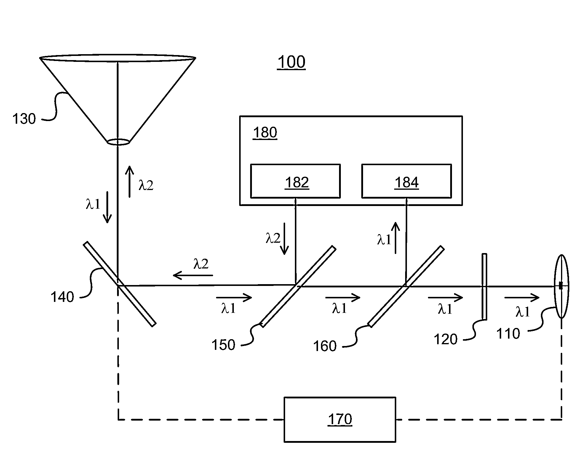
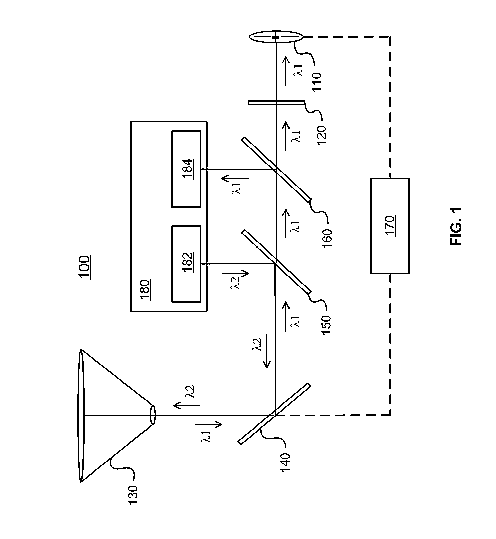
[0020]Adaptive optics systems that compensate for wavefront aberrations typically represent a significant production cost to Free Space Optical (FSO) system manufacturers. For example, a typical adaptive optics system may include a deformable mirror to perform wavefront correction, lenses, mirrors, beamsplitters, detectors, amplifiers, a control loop, and the like. Thus, a low cost, reliable, aberration correction system is desirable.

[0021]A low cost, high reliability system for correcting aberrations in optical signals is disclosed. The system uses a tip-tilt correction system that is more cost effective than a higher-order correction system. Such a system trades-off a higher level of correction for a lower production cost. Such a system also has a better link margin, meaning that it can operate efficiently in a wide range of environmental conditions. Due to the reduced cost of a tip tilt correction system vs. a higher order correction system, budget that would...


PUM


Abstract

A low cost, high reliability system for correcting aberrations in optical signals is disclosed. A foreoptic assembly, such as a telescope, receives an incoming optical signal and directs it to an active optical element, such as a fast steering mirror. The incoming optical signal is diffracted by a diffractive optical element to shape the image that is formed at a wavefront sensor, such as a quad-cell. The wavefront sensor measures a tip-tilt aberration of the incoming optical signal and the active optical element is adjusted to correct the measured aberration. An outgoing optical signal can be transmitted along substantially the same optical path as the incoming optical signal, but in the opposite direction. Thus, the aberration measured from the incoming optical signal can be automatically accounted for in the outgoing optical signal.

Description

CROSS-REFERENCE TO RELATED APPLICATIONS[0001]This application claims the benefit of U.S. Provisional Patent Application No. 61 / 771,851, entitled “Simple Low Cost Tip-Tilt Wavefront Sensor Having Extended Dynamic Range,” filed on Mar. 2, 2013, which is hereby incorporated by reference in its entirety.BACKGROUND[0002]This invention relates generally to Free Space Optical (FSO) communications, and in particular to correction of tip-tilt aberrations in FSO signals.[0003]FSO performance depends upon several factors, including the atmospheric seeing condition, weather, and the local environment. Atmospheric seeing is generally quantified by the length over which the phase of an optical wavefront in the propagation path has 1 radian RMS variance, as described by the Fried parameter, ro. Atmospheric seeing can also be expressed as an angle (e.g., in radians), determined by the mean beam divergence caused by the atmosphere.[0004]Atmospheric seeing is a function of the atmospheric refractive ...

Claims


Application Information

Patent Timeline
Patent Type & Authority Applications(United States)
IPC IPC(8): H04B10/2507
CPCH04B10/2507H04B10/1125
Inventor NORTHCOTT, MALCOLM J.GRAVES, J. ELONFLEISCHER, SIEGFRIEDZAMBON, PAOLOTUTTLE, JEFFREYCHANG, REBECCA
Owner EOS DEFENSE SYST USA INC
Features
  • R&D
  • Intellectual Property
  • Life Sciences
  • Materials
  • Tech Scout
  • Unparalleled Data Quality
  • Higher Quality Content
  • 60% Fewer Hallucinations
Learn More