

Paddle shaft length adjustment device
a technology of length adjustment and paddle shaft, which is applied in the direction of rod connection, marine propulsion, vessel construction, etc., can solve the problems of inability to adjust the length or angle of the first and second shafts, the length of the first shaft cannot be adjusted to conform to the body size of the user, and the first shaft continuously remains at the reduced diameter, etc., to achieve convenient assembly, reduce the diameter of the contractible pipe portion, and facilitate the effect of rowing stability
Inactive Publication Date: 2014-09-04
WOOSUNG I B
View PDF17 Cites 14 Cited by
- Summary
- Abstract
- Description
- Claims
- Application Information
AI Technical Summary
Benefits of technology
The present invention provides a paddle shaft length adjustment device that can be used with different types of paddles, including non-elastic material and elastic material. The device ensures stability and ease of use during rowing by preventing movement of the paddles in longitudinally and rotationally, and also allows for quick position coincidence between the connection parts. Additionally, the device includes a circumferential elongated slot and a clamping member to further enhance the connection strength of the paddles and prevent accidents.
Problems solved by technology
The conventional paddle having the above described configuration, however, has a problem in that the single shaft is beyond length adjustment, and therefore the length of the shaft cannot be adjusted to conform to the body size of a user.
However, in a case in which the first and second shafts are fabricated using a non-elastic material, such as, for example, aluminum, after interconnection of the first and second shafts, the first shaft continuously remains at the reduced diameter because it has no resilience.
Consequently, in the case of the first shaft fabricated using a material having no resilience, the connection end portion of the first shaft continuously remains at the reduced inner diameter, which makes it impossible to repeatedly adjust the length or angle of the first and second shafts.
In addition, due to the fact that the connector pipe provided with the clamping member is adhesively bonded to the connection end portion of the first shaft using the adhesive, coupling between the connector pipe and the first shaft is troublesome and time consuming.
Method used
View moreImage
Smart ImageViewing Examples

Examples
Embodiment Construction
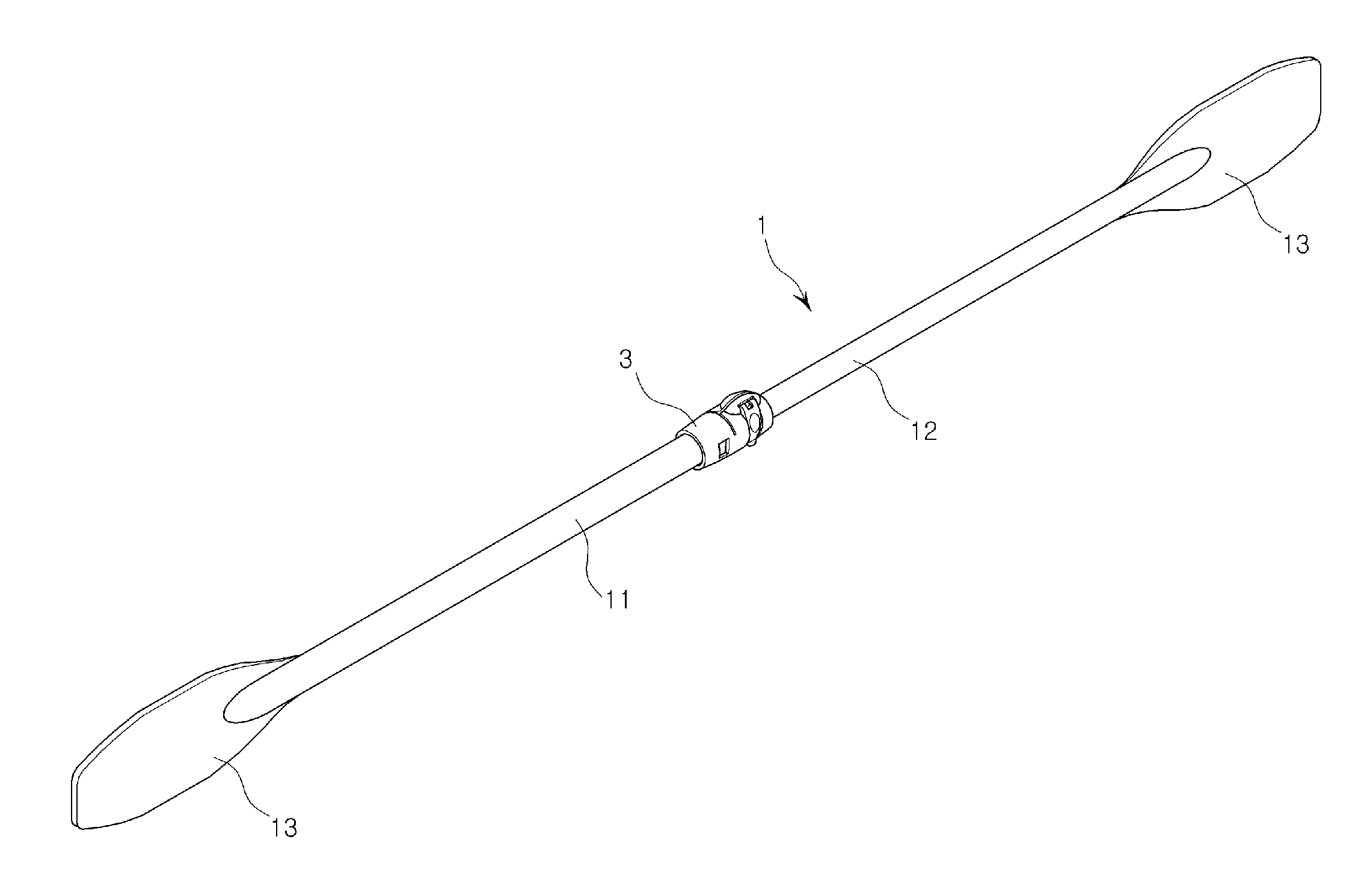
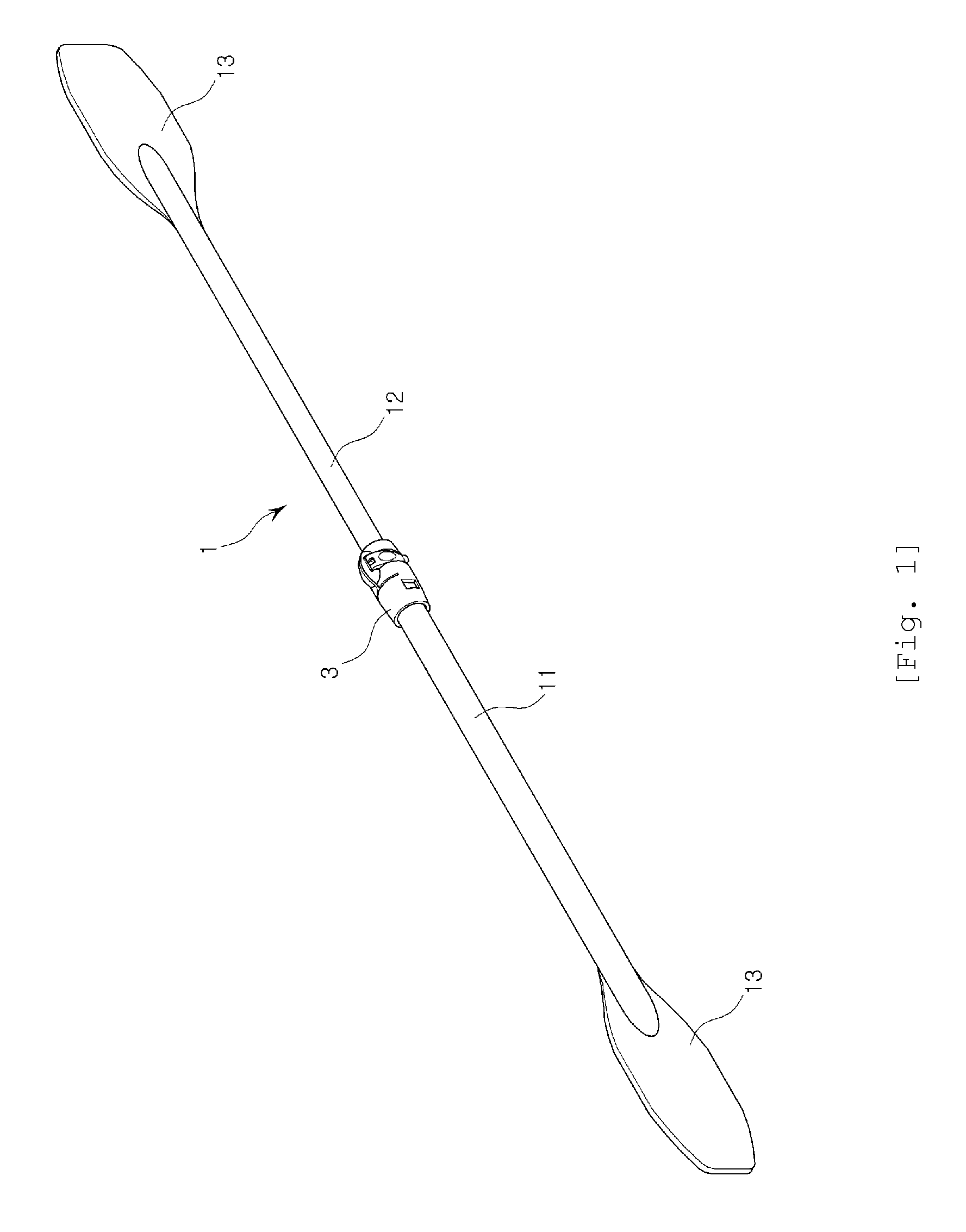
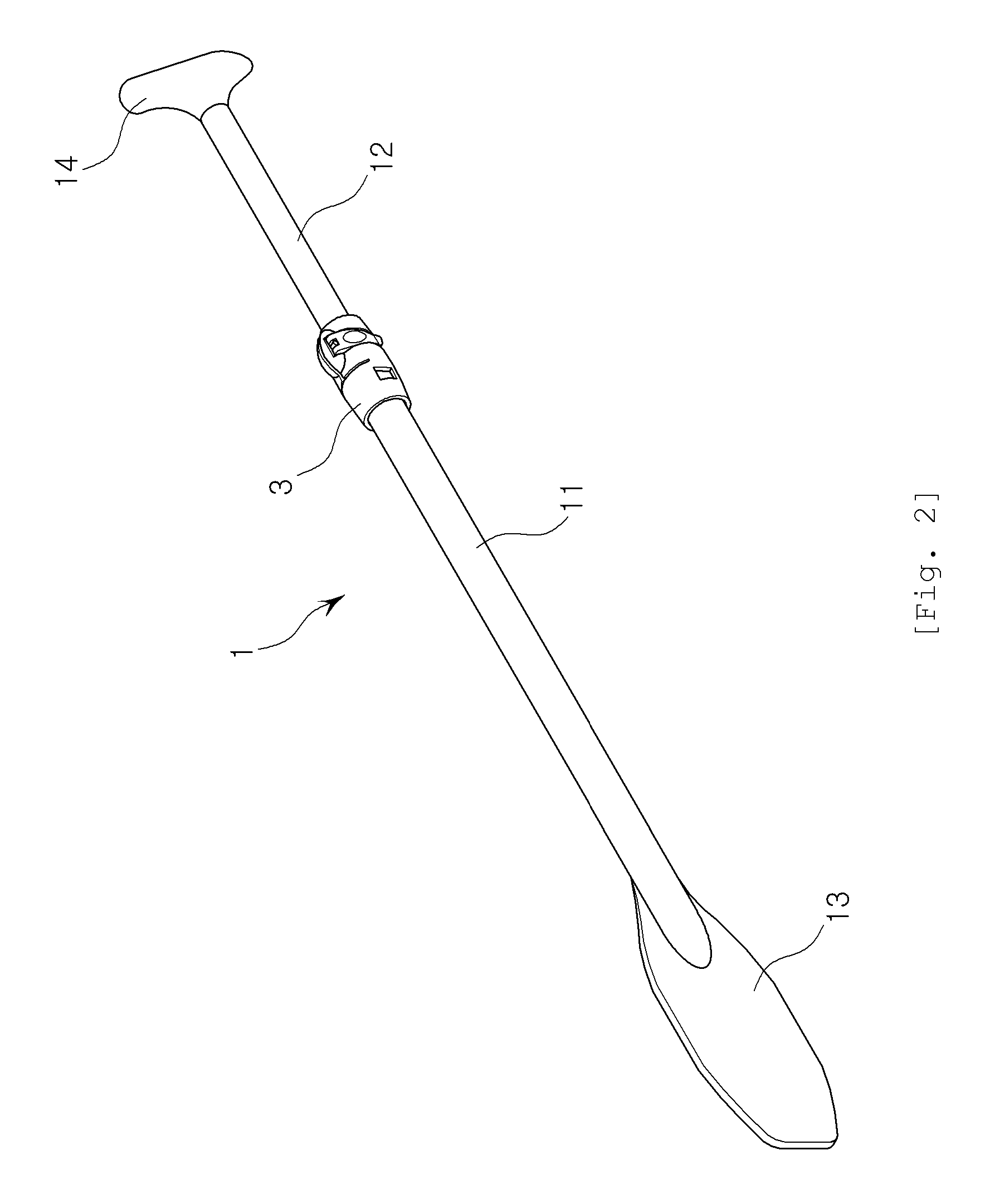
] 1: paddle shaft 11: first shaft111: insertion recess 12: second shaft 13: blade 14: handle 2: snap insertion hole 3: connector pipe 31: boundary wall311: projection 32: expandable pipe portion321: inner circumferential surface 33: contractible pipe portion331: longitudinal elongated slot,332: circumferential elongated slot,333: inner circumferential surface 4: snap type retainer 41: rectangular hole 42: elastic snap plate 5: clamping member 51: domed reinforcement portion 52: through-hole 53: push face 54: operating shaft 55: hinge shaft 56: securing lever561: cam face
Login to View More PUM
 Abstract
Disclosed is a paddle shaft length adjustment device in which a connection end portion of a large-diameter first shaft is connected and secured to a connector pipe via simplified insertion to ensure easy assembly between the first shaft and the connector pipe, and a second shaft is secured by reducing the diameter of a contractible pipe portion of the resilient connector pipe, thereby allowing the length adjustment device to be repeatedly used with a paddle shaft formed of a non-elastic material, such as aluminum. The paddle shaft length adjustment device includes snap insertion holes perforated in the front and rear sides of a connection end portion of a tubular first shaft, a second shaft shaped to be inserted into the first shaft, a connector pipe consisting of, on the basis of a boundary wall formed at a middle position of an inner bore thereof, an expandable pipe portion at one side of the boundary, into which the connection end portion of the first shaft is inserted, and a contractible pipe portion at the other side of the boundary, into which the second shaft to be inserted into the first shaft is inserted such that an outer circumferential surface of the second shaft comes into close contact with an inner circumferential surface of the contractible pipe portion, the connector pipe having a longitudinal elongated slot perforated in the top of the contractible pipe portion, front and rear snap type retainers provided at the front and rear sides of the expandable pipe portion and configured to be snap fitted into the snap insertion holes perforated in the front and rear sides of the first shaft, and a clamping member provided at the contractible pipe portion of the connector pipe, the clamping member securing the second shaft to the contractible pipe portion by reducing the width of the elongated slot, and consequently reducing the diameter of the contractible pipe portion.
Description
TECHNICAL FIELD[0001]The present invention relates to a length adjustment device for a paddle shaft, and more particularly to a paddle shaft length adjustment device, in which a connection end portion of a first shaft having a large diameter is connected and secured to a connector pipe via simplified insertion, and a second shaft is directly secured to a contractible pipe portion of the resilient connector pipe under reduction in the diameter of the contractible pipe portion, whereby the paddle shaft length adjustment device may be repeatedly used with a paddle shaft formed of a non-elastic material, such as aluminum.BACKGROUND ART[0002]Generally, boats are small ships having no deck and more particularly are small vessels for transporting people and cargo or small ships for specialized use, such as pleasure and racing. These boats are divided into a short boat shaped to permit propulsion using a paddle shaft by manpower, and a yacht as a sailboat shaped to permit propulsion by wind...
Claims
Login to View More Application Information
Patent Timeline
 Patent Type & AuthorityApplications(United States)
IPC IPC(8): B63H16/04F16B7/10
CPCF16B7/10B63H16/04F16B7/1454Y10T403/32467F16B7/04
InventorLEE, HEE JAE
OwnerWOOSUNG I B