Machine tool mounted mist collector with filter clamp

Active Publication Date: 2014-09-11
INDAL TOOL & DIE
View PDF2 Cites 10 Cited by
  • Summary
  • Abstract
  • Description
  • Claims
  • Application Information

AI Technical Summary

Benefits of technology

The present invention provides a system and method for removing cooling liquid from a mist. The system includes a baffle filter with layers of baffles to collect and output cooling liquid, an air filter to remove pollutants from the air, and a filter clamp to hold the air filter in place. The method involves receiving the cooling mist, passing it through two mist filters to remove the cooling liquid droplets, using an absorbent layer to absorb unrecoverable oil, and outputting the demisted air through an air filter. The technical effects of this invention include improved air quality, reduced cooling liquid waste, and efficient cooling system design.

Problems solved by technology

These tools may produce a high rate of motion or rotation.
As the tool interacts with a work material, the high rate of motion may lead to high amounts of frictional heating.
This heating may damage the tool, the work material or both.
Nevertheless, there are a number of drawbacks associated with the use of cooling liquid.
In particular, the motion of the tool tends to scatter the cooling liquid.
This can result in cooling liquid causing a large mess in the immediate area.
In addition, it can make it more difficult to recover the cooling liquid.
However, the disruption of the cooling liquid stream can result in loss of cooling liquid.
This can lead to a loss of efficiency as the cooling liquid may not be given sufficient time to be cooled before being recirculated.
Further, it can lead to greater expense as the cooling liquid needs to be replaced.
This cooling mist can enter air intakes of the machine tool or other machines in the nearby area, which can foul the operation of the machines.
In addition, it can be inhaled by workers in the immediate area, causing respiratory or other health problems.

Method used


Image

  • Machine tool mounted mist collector with filter clamp
  • Machine tool mounted mist collector with filter clamp
  • Machine tool mounted mist collector with filter clamp

Examples


Embodiment Construction

[0008]This Summary is provided to introduce a selection of concepts in a simplified form that are further described below in the Detailed Description. This Summary is not intended to identify key features or essential characteristics of the claimed subject matter, nor is it intended to be used as an aid in determining the scope of the claimed subject matter.

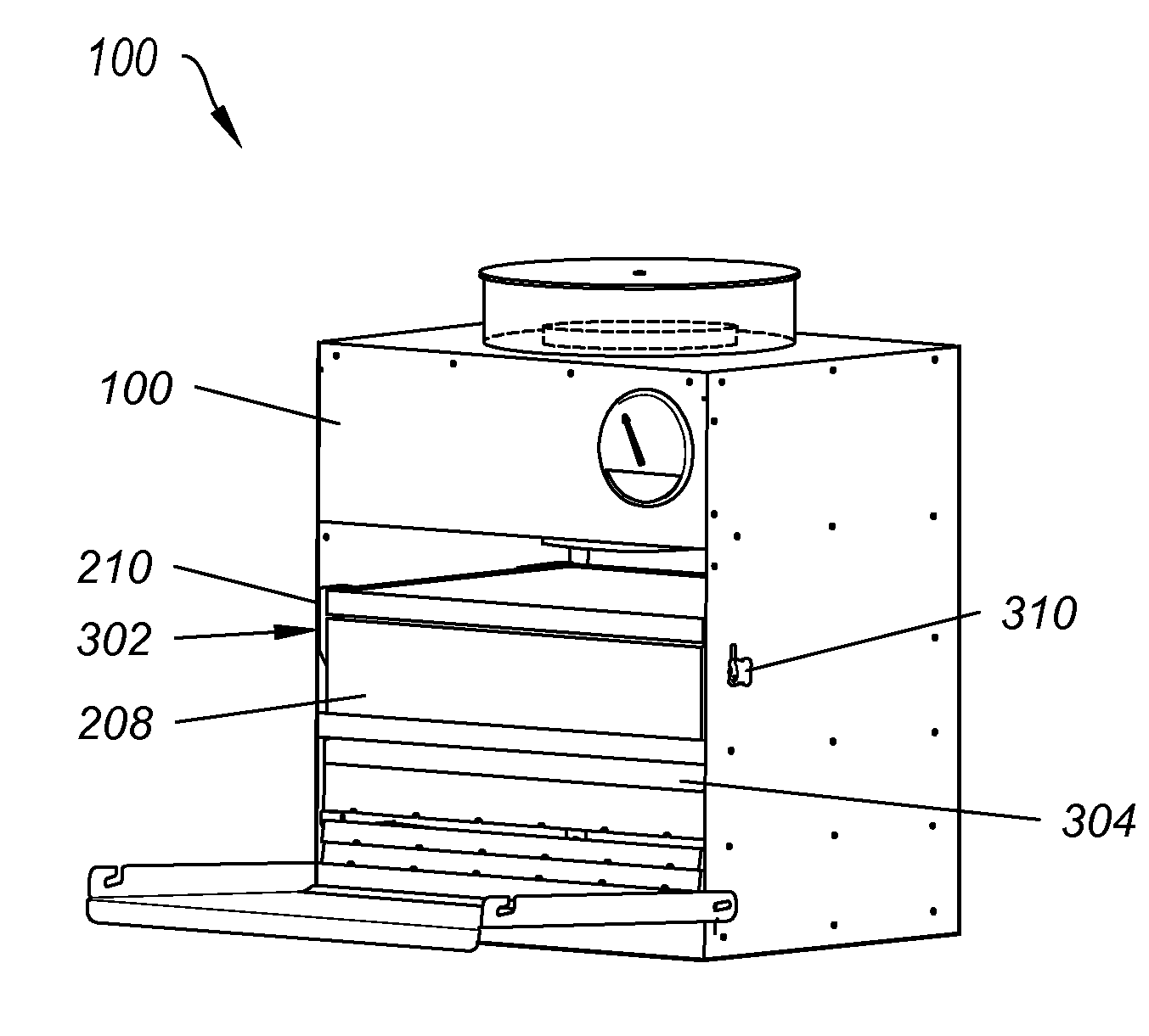
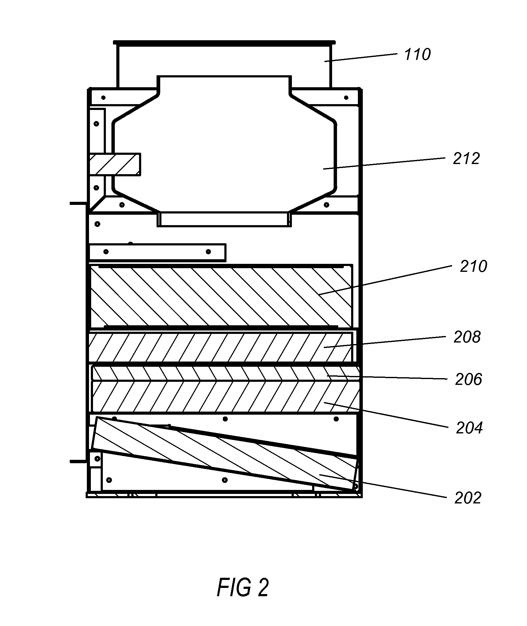
[0009]One example embodiment includes a system for removing cooling liquid from a mist. The system includes an intake, where the intake is configured to receive the cooling mist and a baffle filter including a plurality of overlapping and offset layers of baffles, the baffle filter configured to collect and output cooling liquid from the cooling mist. The system also includes a mesh positioned vertically above the baffle and configured to drip cooling liquid collected thereon onto the baffle filter and an air filter, where the air filter is configured to remove a portion of pollutants from the demisted air. The system further inc...


PUM

PropertyMeasurementUnit
Pressureaaaaaaaaaa
Water solubilityaaaaaaaaaa

Abstract

A system for removing cooling liquid from a mist. The system includes an intake, where the intake is configured to receive the cooling mist and a baffle filter including a plurality of overlapping and offset layers of baffles, the baffle filter configured to collect and output cooling liquid from the cooling mist. The system also includes a mesh positioned vertically above the baffle and configured to drip cooling liquid collected thereon onto the baffle filter and an air filter, where the air filter is configured to remove a portion of pollutants from the demisted air. The system further includes a filter clamp configured to hold the air filter in place and an exhaust, where the exhaust is configured to output the demisted air.

Description

CROSS-REFERENCE TO RELATED APPLICATIONS[0001]This application is a continuation-in-part of, and claims the benefit of and priority to, U.S. Non-Provisional patent application Ser. No. 13 / 283,467 filed on Oct. 27, 2011, which application is incorporated herein by reference in its entirety.[0002]U.S. Non-Provisional patent application Ser. No. 13 / 283,467 claims the benefit of and priority to U.S. Provisional Patent Application Ser. No. 61 / 407,445 filed on Oct. 28, 2010, which application is incorporated herein by reference in its entirety.BACKGROUND OF THE INVENTION[0003]Cooling liquid is commonly used with machine tools. These tools may produce a high rate of motion or rotation. As the tool interacts with a work material, the high rate of motion may lead to high amounts of frictional heating. This heating may damage the tool, the work material or both. To prevent his damage a cooling liquid is often circulated over the tool and work material. The circulating cooling liquid removes th...

Claims


Application Information

Patent Timeline
IPC IPC(8): B01D46/00B01D45/08B01D50/00
CPCB01D50/002B01D45/08B01D46/0031B01D46/0036B01D46/10B01D50/20
Inventor CACCIOTTI, PAUL
Owner INDAL TOOL & DIE
Why Eureka
Try Eureka