Supercharge Your Innovation With Domain-Expert AI Agents!

X-ray diffraction method of mapping grain structures in a crystalline material sample, and an x-ray diffraction apparatus

a crystalline material and diffraction method technology, applied in the field of x-ray diffraction method of mapping grain structure in crystalline material sample, to achieve the effect of reliable acquisition and calculation

Active Publication Date: 2014-09-11
XNOVO TECH APS
View PDF1 Cites 2 Cited by
  • Summary
  • Abstract
  • Description
  • Claims
  • Application Information

AI Technical Summary

Benefits of technology

The invention aims to improve the collection and calculation of data from complicated materials with crystal structures. The technical effect is to provide a reliable and effective way to work with these samples.

Problems solved by technology

It is explained in the article that overlapping diffraction contrasts present a problem and that the sample consequently had to have only little grain orientation spread, grains of approximately the same size and tailored transverse sample dimensions in order to limit the probability of spot overlap.

Method used


Image

  • X-ray diffraction method of mapping grain structures in a crystalline material sample, and an x-ray diffraction apparatus
  • X-ray diffraction method of mapping grain structures in a crystalline material sample, and an x-ray diffraction apparatus
  • X-ray diffraction method of mapping grain structures in a crystalline material sample, and an x-ray diffraction apparatus

Examples


Embodiment Construction

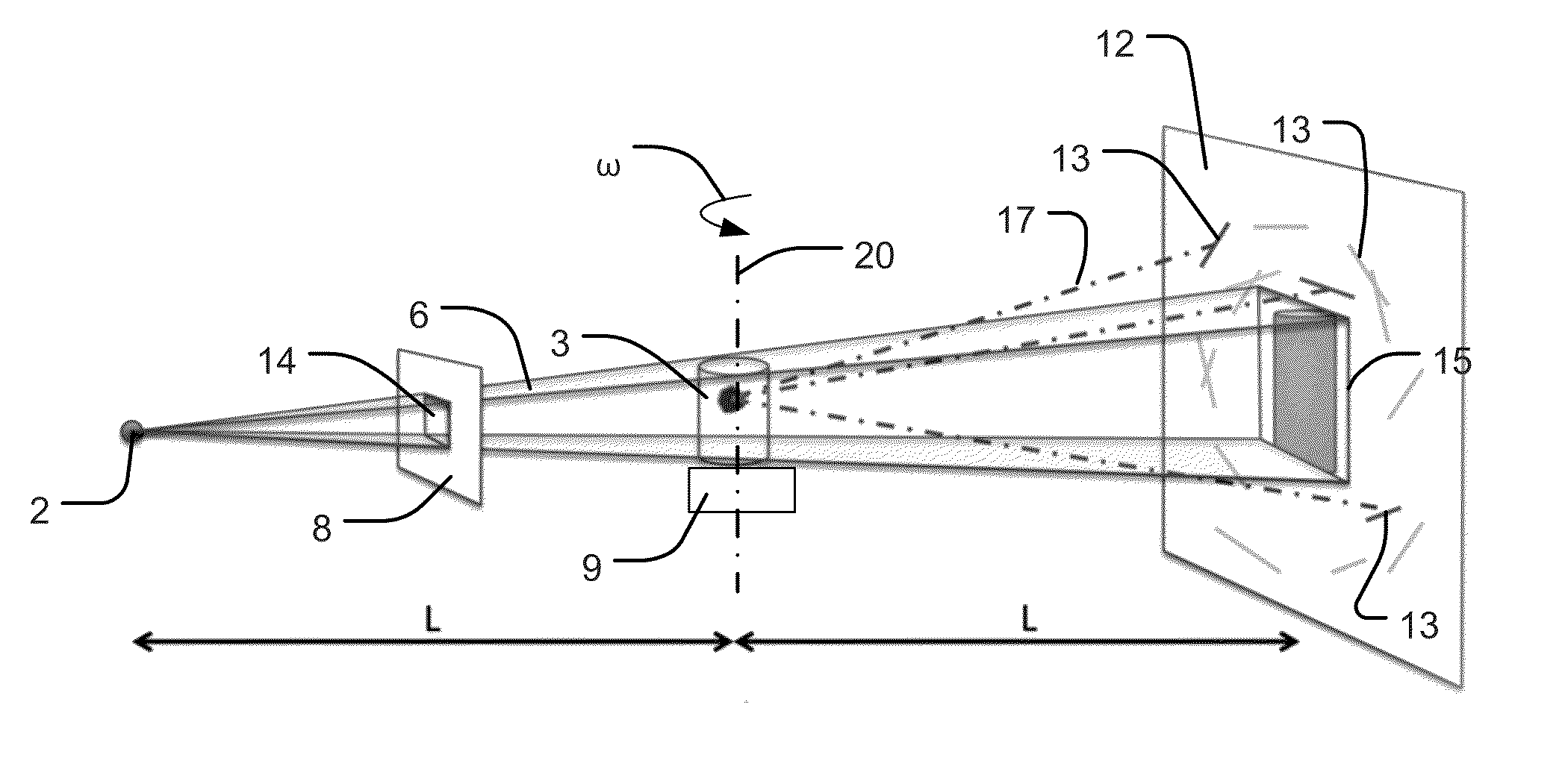
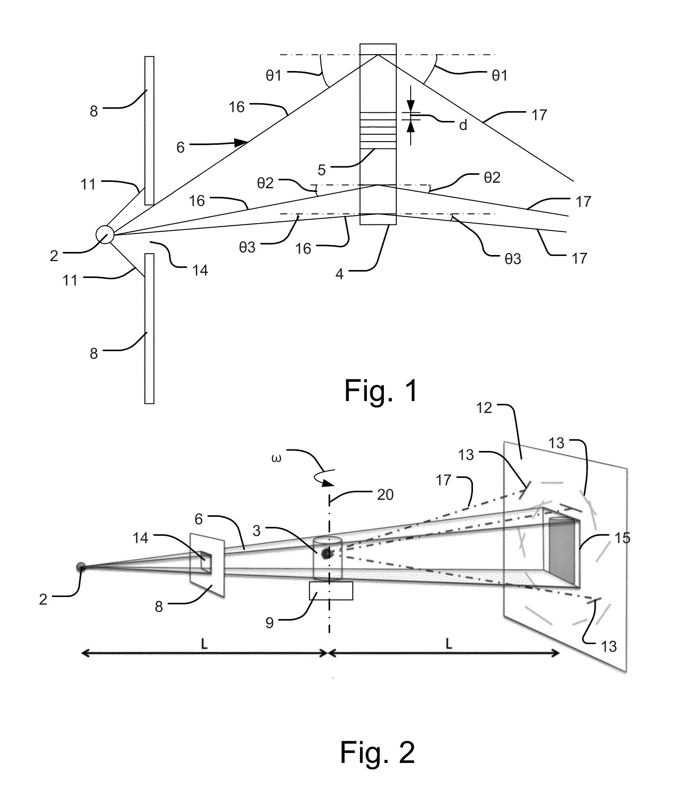
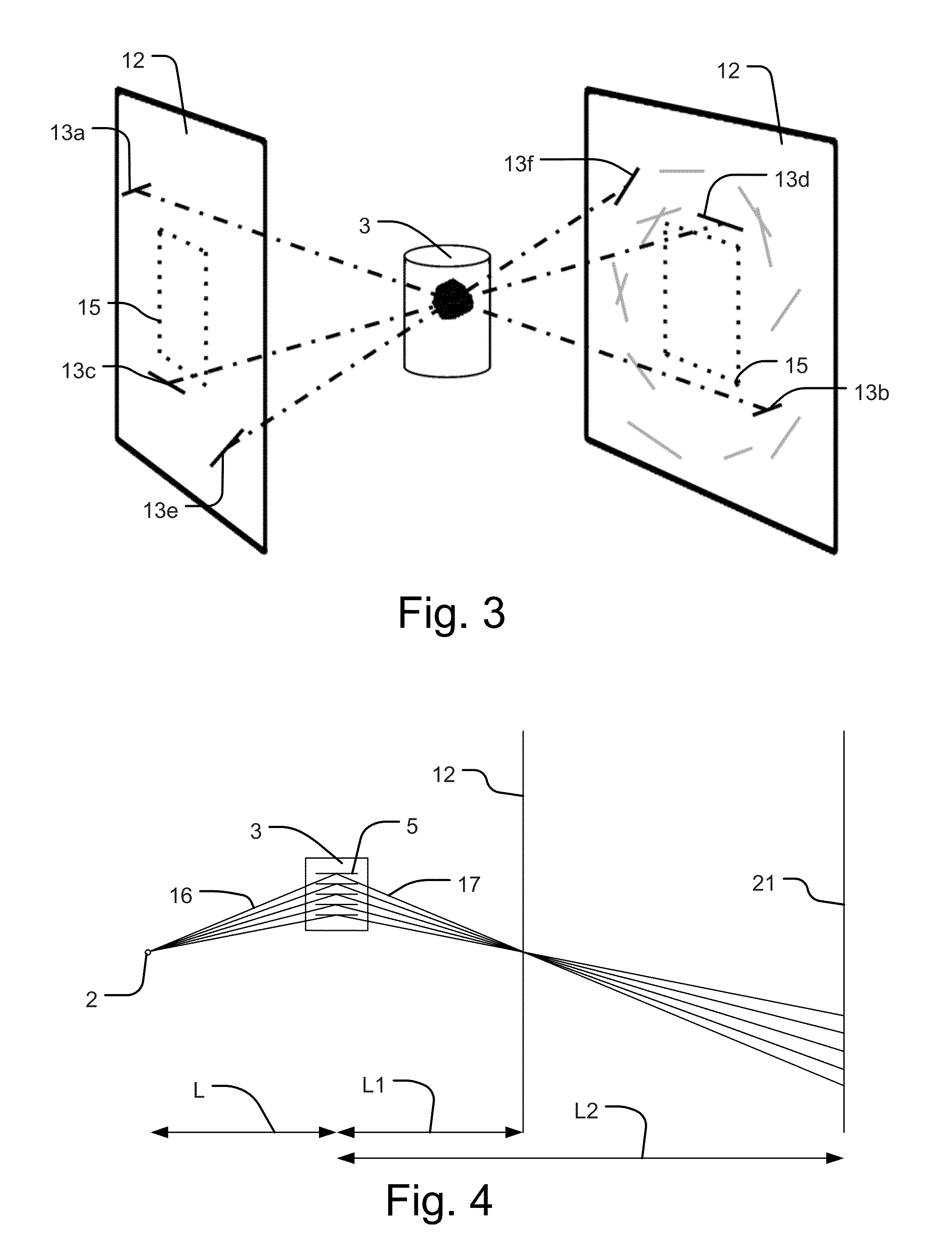
[0044]An embodiment of an X-ray diffraction apparatus is generally denoted 1 in FIG. 7 and it has a data acquisition unit 24 and a data analysing unit 25 that may be operated by a human operator 26. The data acquisition unit comprises an X-ray source 2, a staging device 9 and a first detector 12, and as illustrated in FIG. 2 these parts are located with the source at one side of the staging device and the detector at the other side thereof.

[0045]The X-ray source 2 provides a polychromatic X-ray beam 6 in a beam path. The beam is preferably passed through a pinhole opening in a diaphragm in the source 2, which pinhole opening is much smaller than the dimensions of the beam at the staging device 9, so that source 2 can be considered a point source. The X-ray source is a so-called laboratory X-ray source, and such a source is very different from a synchrotron X-ray source used for mapping grain structures in a polycrystalline material. The synchrotron source is a giant structure that p...


PUM

PropertyMeasurementUnit
Bragg angleaaaaaaaaaa
distanceaaaaaaaaaa
distanceaaaaaaaaaa

Abstract

An X-ray diffraction method of mapping grain structures in a polycrystalline material sample, where an X-ray detector detects substantially line-shaped segments from beams diffracted from at least some of the grains. A processing device analyses values received from the X-ray detector and identifies at least the position and the length of the line-shaped segments. The line-shaped segments are paired as originating from diffractions from the same grain and the positions of the paired line-shaped segments are used in determining the crystallographic grain position of this grain within in the polycrystalline material sample. The length of the paired line-shaped segments is used in determining a width of this grain.

Description

CROSS-REFERENCE TO RELATED APPLICATIONS[0001]Not ApplicableSTATEMENT REGARDING FEDERALLY SPONSORED RESEARCH OR DEVELOPMENT[0002]Not ApplicableREFERENCE TO A MICROFICHE APPENDIX[0003]Not ApplicableBACKGROUND OF THE INVENTION[0004]In a first aspect the present invention relates to an X-ray diffraction method of mapping grain structures in a crystalline material sample, where an X-ray source provides a polychromatic X-ray beam in a beam path, in which beam path the polychromatic X-ray beam is divergent, a staging device positions the crystalline material sample in the beam path, and an X-ray detector detects a plurality of diffracted X-ray beams leaving the crystalline material sample.[0005]The article “A focusing Laue diffractometer for investigation of bulk crystals” by Matthias Stockmeier and Andreas Mager!, Journal of Applied Crystallography (2008), 41, 754-760, describes a method of this kind where the crystalline material sample is a single crystal. It is well-known that diffract...

Claims


Application Information

Patent Timeline
Patent Type & Authority Applications(United States)
IPC IPC(8): G01N23/207
CPCG01N23/207G01N23/205G01N2223/056G01N2223/3306G01N2223/605G01N2223/606G01N2223/607G01N2223/648G01N2223/649
Inventor LAURIDSEN, ERIK MEJDALPOULSEN, STEFAN OTHMAR
Owner XNOVO TECH APS
Features
  • R&D
  • Intellectual Property
  • Life Sciences
  • Materials
  • Tech Scout
  • Unparalleled Data Quality
  • Higher Quality Content
  • 60% Fewer Hallucinations
Learn More