Aircraft braking early warning system

a technology of early warning system and aircraft, which is applied in the direction of traffic control system, aircraft indicators, analog and hybrid computing, etc., can solve the problems of contaminated runways, inherently risky modes of travel, and pilots often feeling pressure,

Active Publication Date: 2014-09-11
3RD MILLENNIUM SOLUTIONS
View PDF1 Cites 53 Cited by
  • Summary
  • Abstract
  • Description
  • Claims
  • Application Information

AI Technical Summary

Benefits of technology

[0008]The following presents a simplified summary of the invention in order to provide a basic understanding of some example aspects of the invention. This summary is not an extensive overview of the invention. Moreover, this summary is not intended to identify critical elements of the invention nor delineate the scope of the invention. The sole purpose of the summary is to present some concepts of the invention in simplified form as a prelude to the more detailed description that is presented later.

Problems solved by technology

Aviation is an inherently risky mode of travel in bad weather.
In today's society where time is a valuable asset, pilots often feel pressured to land their aircraft in weather conditions they might otherwise wish to avoid.
A contaminated runway may present hazardous conditions for landing aircraft because the effectiveness of wheel brakes may be reduced or negated by a low coefficient of friction (resulting from the ground contamination) between the runway surface and the wheels of the landing aircraft.
Even so, individual pilot experiences are different and reports of this kind are very subjective.
The subjective nature of these observations limits their usefulness.
This measurement is difficult to interpret by an airplane pilot flying an aircraft with a varying and modulating slip ratio as in an aircraft anti-skid braking system (ASBS), and thus has limited applicability to assist the pilot in safely landing their aircraft.
While this would be beneficial to a braking system which incorporated this idea, it is of limited use to current aircraft braking systems as they do not have the capabilities to ‘seek out’ and then maintain the maximum runway friction wheel slip ratio.

Method used


Image

  • Aircraft braking early warning system
  • Aircraft braking early warning system

Examples


Embodiment Construction

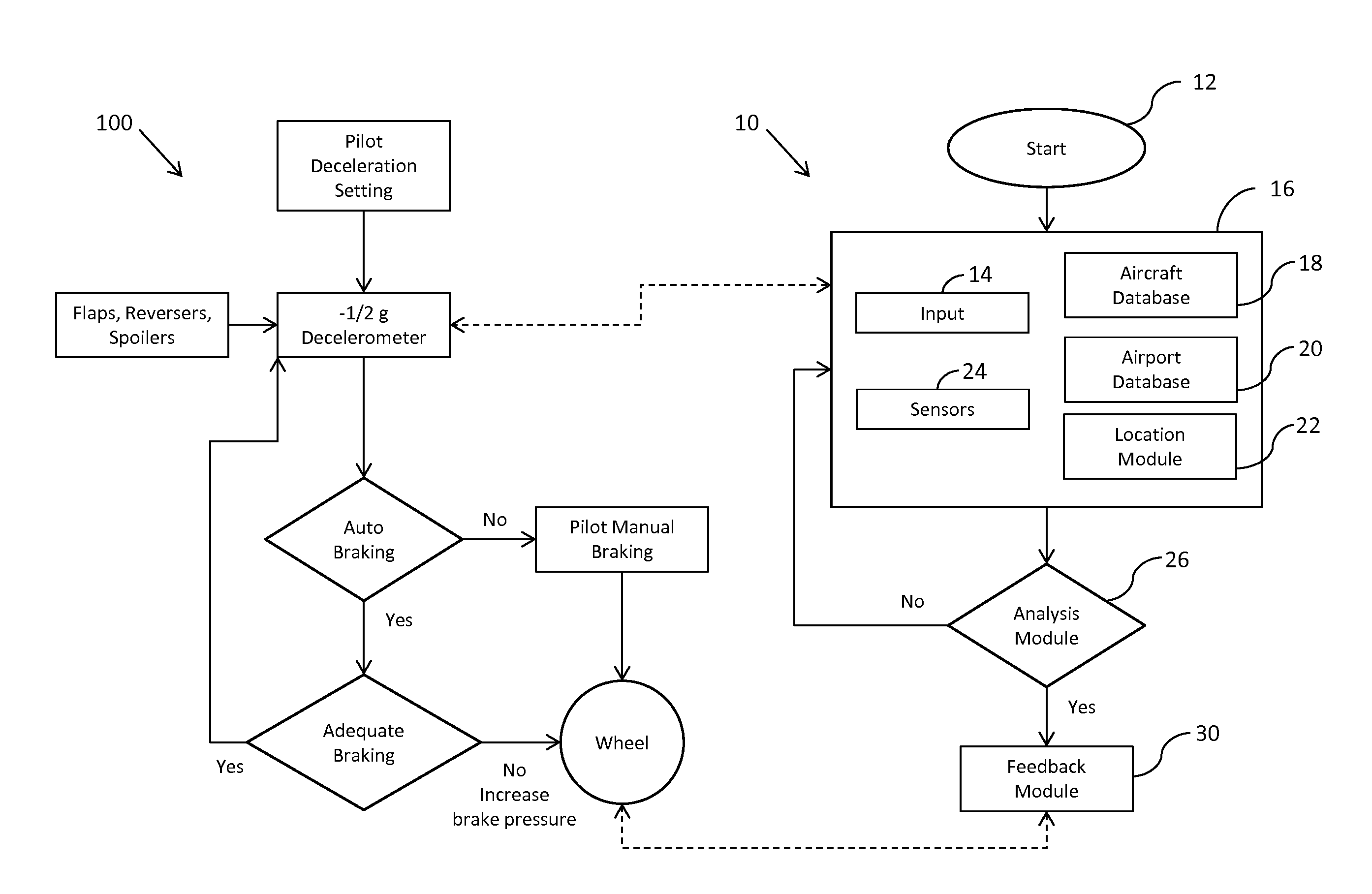
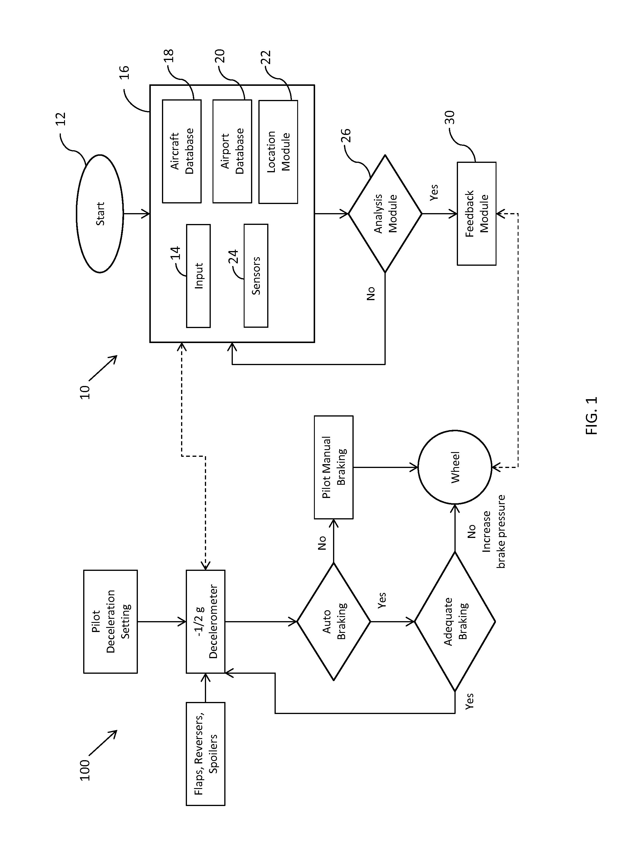
[0014]Example embodiments that incorporate one or more aspects of the present invention are described and illustrated in the drawings. These illustrated examples are not intended to be a limitation on the present invention. For example, one or more aspects of the present invention can be utilized in other embodiments and even other types of devices. Moreover, certain terminology is used herein for convenience only and is not to be taken as a limitation on the present invention. Still further, in the drawings, the same reference numerals are employed for designating the same elements.

[0015]The present application provides methods and apparatus for determining the instantaneous and dynamic vehicle braking effectiveness of an actual aircraft that is performing a landing procedure, as a result of the actual support surface conditions and other environmental concerns, to permit a vehicle operator (e.g., an aircraft pilot) to better understand how a vehicle wheel braking system is actuall...


PUM


Abstract

A method provides alert information, regarding an aircraft wheel braking system, to an operator of an aircraft during an aircraft landing. An input of a target deceleration rate for the landing aircraft is received prior to the aircraft having landed on a ground surface. At least one sensor electronically collects information relevant to a real-time deceleration rate of the aircraft after the aircraft has landed on the ground surface, and the real-time deceleration rate of the aircraft is calculated. The target deceleration rate is compared to the calculated deceleration rate to determine an effectiveness of the aircraft wheel braking system. A visual, audible, or tactile alert is optionally provided to the operator of the aircraft, and data from this system could also be used as an input for various other aircraft safety systems. A system for performing the method is also provided.

Description

CROSS-REFERENCE TO RELATED APPLICATIONS[0001]This application claims the benefit of U.S. Provisional Application No. 61 / 773,533, filed Mar. 6, 2013, the entire disclosure of which is hereby incorporated herein by reference.FIELD OF THE INVENTION[0002]The present invention relates generally to methods and apparatus for determining a predicted vehicle braking operation, and providing real-time feedback to the vehicle operator.BACKGROUND OF THE INVENTION[0003]Aviation is an inherently risky mode of travel in bad weather. Unlike other modes of transportation such as by land or sea where dangerous weather conditions can be avoided by “waiting out the storm”, an aircraft carries a finite amount of fuel to power its engines, and must land at a suitable airport before it runs out of fuel. In addition, the great distances that an aircraft can travel in a relatively short period of time allow for drastically different landing conditions from takeoff to landing. In today's society where time i...

Claims


Application Information

Patent Timeline
Patent Type & Authority Applications(United States)
IPC IPC(8): B64D45/00
CPCB64D45/00B64C25/426B60T8/1703B60T2210/36G08G5/0021G08G5/025
Inventor MCKEOWN, STEPHEN LYLEKLEINSCHMIDT, PETER PAULLAIDMAN, JEFFREY ALAN
Owner 3RD MILLENNIUM SOLUTIONS
Why Eureka
Try Eureka