Supercharge Your Innovation With Domain-Expert AI Agents!

Mask set for double exposure process and method of using the mask set

a mask set and mask technology, applied in the field of multiple exposure technology, can solve the problems of large overlay region of two decomposed patterns, many process issues to overcome, and inability to achieve euvl,

Active Publication Date: 2014-09-11
UNITED MICROELECTRONICS CORP
View PDF4 Cites 3 Cited by
  • Summary
  • Abstract
  • Description
  • Claims
  • Application Information

AI Technical Summary

Benefits of technology

The present invention provides a new mask set for double exposure processes and a method of using it. This mask set consists of two sub-mask patterns that are overlaid in a specific way to create the original target comb mask pattern. The sub-mask patterns have features that align in a specific direction, and may be overlaid in a way that maximizes pattern resolution. The method includes steps of providing a mask pattern, splitting it into two sub-mask patterns, and using them to create a first mask and a second mask with improved pattern resolution. Overall, this invention provides a more robust and precise tool for double exposure processes.

Problems solved by technology

Although there is anticipation that extreme ultraviolet lithography (EUVL) with the wavelength of 13 nm will replace traditional optical lithography, the availability of EUVL remains uncertain due to technical challenges and cost issues.
However, there are still many process issues to overcome in practice.
For example, the large overlay region of two decomposed patterns is prone to suffer film punching problems after the etching process.
Furthermore, in the application of splitting one single comb pattern into two comb patterns, the tooth portion of comb patterns may have inconsistent or asymmetric corner rounding profile due to the different pitches between the teeth.
Besides, for some conventional double exposure method, the resulting target photoresist pattern formed from the two decomposed patterns may lack necessary corner rounding features in connection positions of teeth and base portions due to the perpendicular intersection thereof, thereby introducing potential leakage issue.

Method used


Image

  • Mask set for double exposure process and method of using the mask set
  • Mask set for double exposure process and method of using the mask set
  • Mask set for double exposure process and method of using the mask set

Examples


Embodiment Construction

[0028]In the following detailed description of the invention, reference is made to the accompanying drawings which form a part hereof, and in which is shown, by way of illustration, specific embodiments in which the invention may be practiced. These embodiments are described in sufficient details to enable those skilled in the art to practice the invention. Other embodiments may be utilized and structural, logical, and electrical changes may be made without departing from the scope of the present invention.

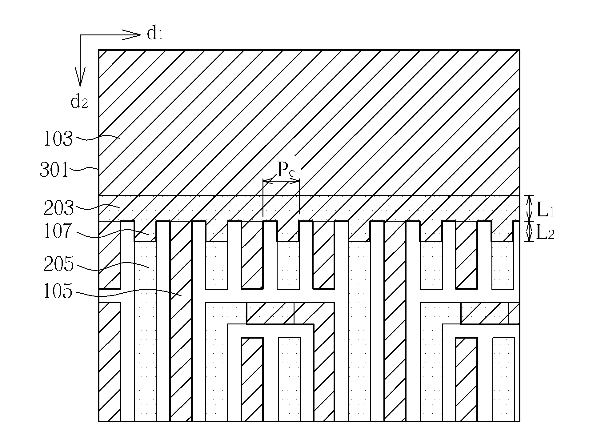
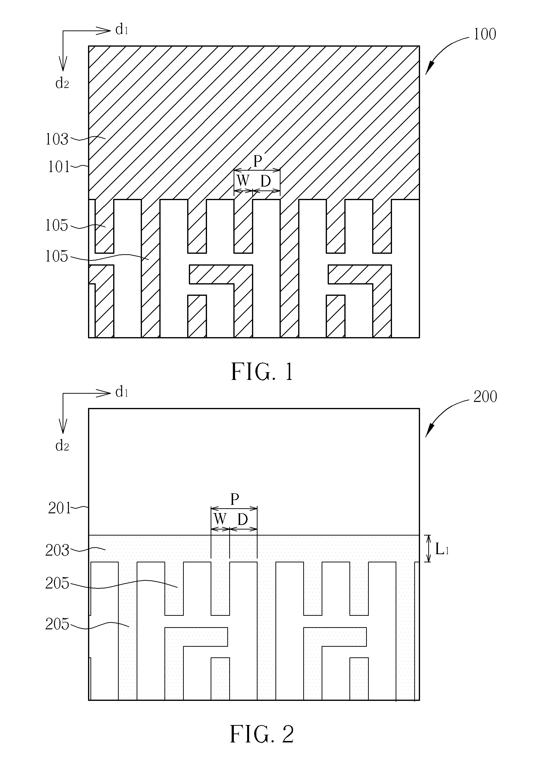
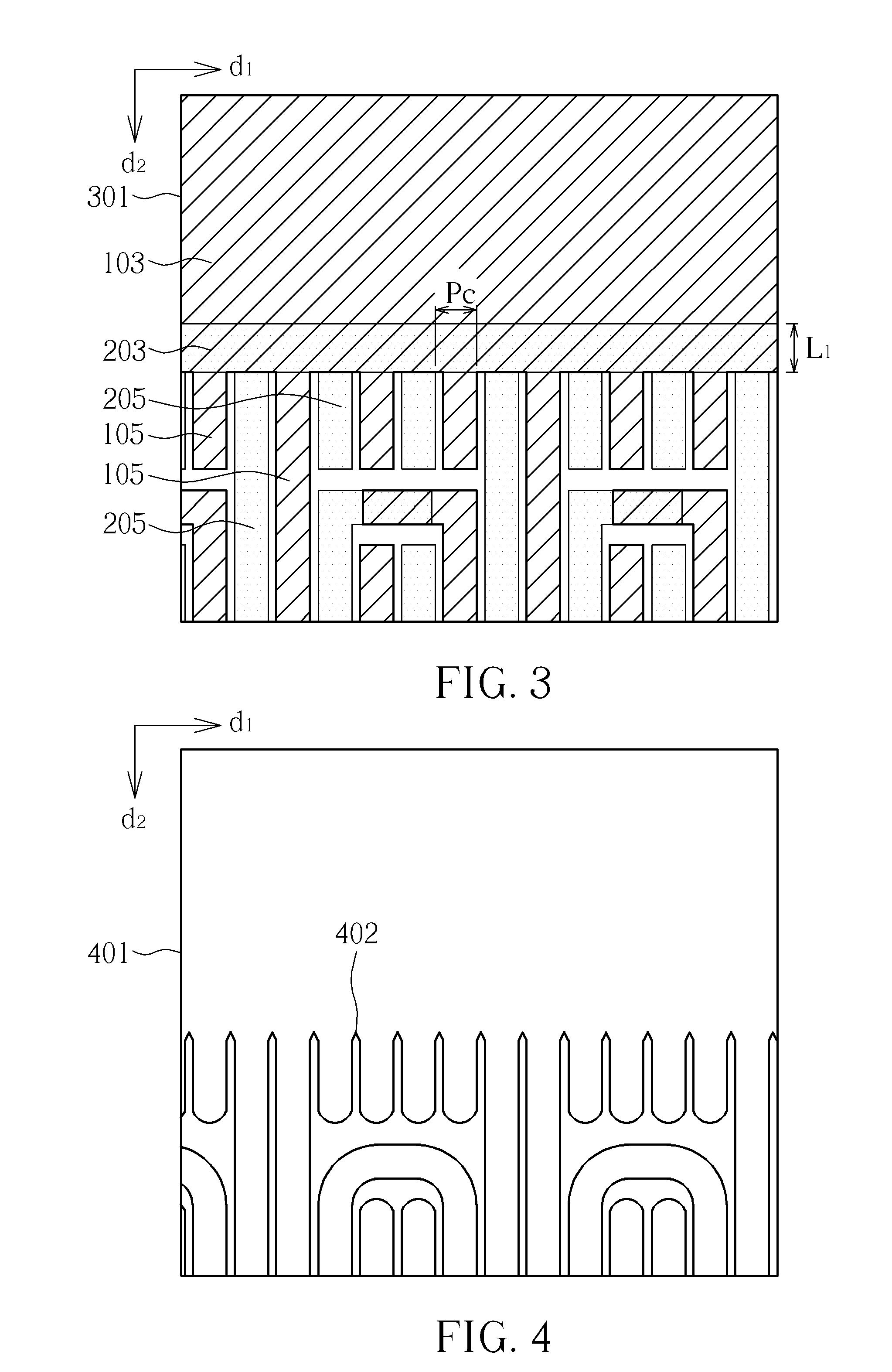
[0029]The embodiments will now be explained with reference to the accompanying drawings to provide a better understanding of the process of the present invention, wherein FIGS. 1-3 are top views illustrating the mask patterns in accordance with the first preferred embodiment of the present invention; FIGS. 5-7 are top views illustrating the mask patterns in accordance with the second preferred embodiment of the present invention.

[0030]The method of present invention relates to a d...


PUM


Abstract

A mask set for double exposure process and method of using said mask set. The mask set is provided with a first mask pattern having a first base and a plurality of first teeth and protruding portions, and a second mask pattern having a second base and a plurality of second teeth, wherein the second base may at least partially overlap the first base such that each of the protruding portions at least partially overlaps one of the second teeth.

Description

CROSS REFERENCE TO RELATED APPLICATIONS[0001]This Continuation-in-Part application claims the benefit of U.S. application Ser. No. 13 / 455,113, which was filed on Apr. 24, 2012 and entitled “MASK SET FOR DOUBLE EXPOSURE PROCESS AND METHOD OF USING THE MASK SET”.BACKGROUND OF THE INVENTION[0002]1. Field of the Invention[0003]The invention relates generally to a multiple exposure technology, and more specifically, to a mask set for double exposure process and the method of decomposing the mask pattern.[0004]2. Description of the Prior Art[0005]Optical lithography is a crucial step in semiconductor manufacturing. The basic principle of optical lithography is quite similar to that of chemistry-based photography. The images of the patterned photo-mask are projected through the high-precision optical system onto the wafer surface, which is coated with a layer of light-sensitive chemical compound, e.g. photo-resist. The patterns are then formed on the wafer surface after complex chemical re...

Claims


Application Information

Patent Timeline
IPC IPC(8): G06F17/50G03F1/00
CPCG03F1/00G06F17/5081G03F1/70G03F7/70466G06F30/398G03F7/20
Inventor KUO, HUI-FANGCHEN, MING-JUITSENG, TING-CHENGWANG, CHENG-TE
Owner UNITED MICROELECTRONICS CORP
Features
  • R&D
  • Intellectual Property
  • Life Sciences
  • Materials
  • Tech Scout
  • Unparalleled Data Quality
  • Higher Quality Content
  • 60% Fewer Hallucinations
Learn More