Cutting machine for producing stacked lamina elements of an electrical machine stator

a technology of stators and cutting machines, applied in the field of electric machines, can solve the problems of long process calendar time and many man hours, and achieve the effects of avoiding non-aligning stacking effectively, improving process reliability, and improving production reliability for stator segments

Active Publication Date: 2014-09-18
SIEMENS GAMESA RENEWABLE ENERGY AS
View PDF2 Cites 0 Cited by
  • Summary
  • Abstract
  • Description
  • Claims
  • Application Information

AI Technical Summary

Benefits of technology

[0013]Generally speaking, according to the described method the process of cutting out the lamina elements and the process of stacking these lamina elements together are combined in such a way that the output of the combined process is a stack of lamina elements which is ready to be bonded together in order to form a stator segment for an electric generator. By combining the process of cutting out and the process of stacking into effectively one process the number of steps in the manufacturing process of laminated stator segments for an electric generator can be reduced. This may make the manufacturing process less complex and less costly.
[0056]The output of the combined process is a stack of lamina elements which is ready to be bonded together in order to form a stator segment for an electric generator. By combining the cutting out and the stacking into effectively one process the number of steps in the manufacturing process of laminated stator segments for an electric generator can be reduced. This may make the manufacturing process less complex and less costly.

Problems solved by technology

This is a very long process that takes long calendar time and requires many man hours.

Method used


Image

  • Cutting machine for producing stacked lamina elements of an electrical machine stator
  • Cutting machine for producing stacked lamina elements of an electrical machine stator
  • Cutting machine for producing stacked lamina elements of an electrical machine stator

Examples


Embodiment Construction

[0062]The illustration in the drawing is schematically. It is noted that in different figures, similar or identical elements are provided with reference signs, which are different from the corresponding reference signs only within the first digit.

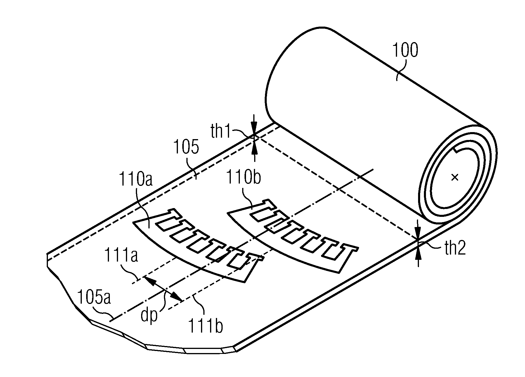
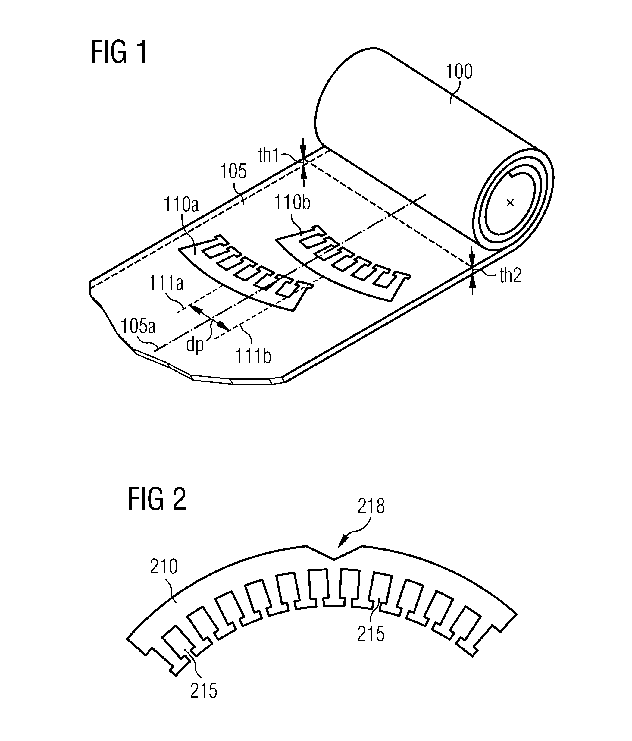
[0063]FIG. 1 shows a punched metal foil 105. According to the embodiment described here the metal foil 105 is made out of steel and has a thickness of approximately 0.5 mm. The foil 105 is partially unrolled from a coil 100 along a longitudinal axis 105a. The longitudinal axis corresponds to a centerline 105a of the foil 105.

[0064]According to the embodiment described here the foil 105 comprises a thickness variance along an axis being perpendicular to the centerline 105a. A first thickness th1 and a second thickness th2 are indicated. The difference between the first thickness th1 and the second thickness th2 may be for instance 0.01 mm or 0.05 mm.

[0065]In order to even out thickness variances at least partially, a first cut-out 110a for a...


PUM

PropertyMeasurementUnit
widthaaaaaaaaaa
lengthaaaaaaaaaa
thicknessaaaaaaaaaa

Abstract

A cutting machine for producing lamina elements includes a cutting mechanism for cutting out a first lamina element from a foil at a first position within the foil and for cutting out a second lamina element from the foil at a second position within the foil. With respect to a centerline of the foil the first position has a first distance and the second position has a second distance being different to the first distance. The cutting machine is adapted for releasing the cut out first lamina element and the cut out second lamina element, such that by utilizing the gravitational force the first lamina element and the second lamina element are transferred to a container, in which they are arranged in a stacked and in an aligned manner with respect to each other.

Description

CROSS REFERENCE TO RELATED APPLICATIONS[0001]This application is a divisional application of U.S. patent application Ser. No. 12 / 706,996 filed Feb. 17, 2010, which claims priority of European Patent Office application No. 09003680.7 EP filed Mar. 13, 2009. All the applications are incorporated by reference herein in its entirety.FIELD OF INVENTION[0002]The present invention generally relates to the field of electrical machines. In particular the present invention relates to a cutting machine for producing lamina elements of a stator of an electric machines.BACKGROUND OF INVENTION[0003]A stator of an electric generator typically comprises a laminated structure being composed of a plurality of lamina elements. The lamina elements are usually punched out of a sheet of magnetizable metal such as for instance steel. The individual lamina elements are transported from a punching machine to a different location where they are stacked. This transportation procedure is typically carried out ...

Claims


Application Information

Patent Timeline
Patent Type & Authority Applications(United States)
IPC IPC(8): H02K15/02
CPCH02K15/024B21D28/22B21D43/22Y02E10/72Y10T29/49009Y10T29/5137Y10T29/53143
Inventor STIESDAL, HENRIK
Owner SIEMENS GAMESA RENEWABLE ENERGY AS
Why Eureka
Try Eureka