Methods and systems for boost control

a boost control and boost technology, applied in the direction of electric control, machines/engines, mechanical equipment, etc., can solve the problems of increased engine pumping work, confusion of wastegate control loop, and increased exhaust pressure, so as to improve the peak power output

Inactive Publication Date: 2014-09-18
FORD GLOBAL TECH LLC
View PDF7 Cites 50 Cited by
  • Summary
  • Abstract
  • Description
  • Claims
  • Application Information

AI Technical Summary

Benefits of technology

[0003]As one example, wastegate adjustments affect the boost pressure through relatively slow turbocharger dynamics while CSV adjustments, as well as intake throttle adjustments, affect the boost pressure through relatively fast dynamics. Due to the different dynamics, the action of the intake throttle, may have an immediate effect on boost pressure and may confound the wastegate control loop. As a result, the engine may operate, at least temporarily, in or close to a hard or soft surge region. Leaving the CSV open (when possible without degrading engine torque delivery) may alleviate surge tendencies but may lead to elevated exhaust pressures and increased engine pumping work. In addition, fuel economy may be degraded due to extra compressor work needing to be compensated by increased turbine work.
[0004]The inventors herein have identified that some of the above issues may be addressed by a method for a boosted engine system comprising: concurrently adjusting each of a wastegate, a compressor recirculation valve (CCRV), and an intake throttle to provide a desired boost pressure and manifold air flow. In this way, by operating the CCRV actuator in coordination with the intake throttle and the wastegate, a faster and more accurate regulation of boost pressure and engine torque output is achieved.
[0006]As such, due to the slow turbocharger dynamics associated with the actuation of the wastegate, the desired boost pressure change is achieved slowly since the wastegate first needs to accelerate (or decelerate) the turbine and the compressor. Thus, in coordination with the wastegate adjustment, a compressor recirculation valve (CCRV) is adjusted concurrently. Specifically, the CCRV is feed-forward adjusted based on operating conditions and a compressor pressure ratio to move turbocharger operation away from a hard surge limit to within a soft surge region. The CCRV is then feedback adjusted to correct for boost errors resulting from the wastegate adjustment. Since the impact of the CCRV adjustment on boost pressure is substantially immediate, the CCRV and the wastegate can be used together to provide accurate steady state boost pressure regulation in the presence of uncertainties and external disturbances. Likewise, intake throttle adjustments may also be concurrently used to take advantage of the rapid turbocharger dynamics associated with throttle actuation. For example, the intake throttle is adjusted based on a manifold flow rate error resulting from the wastegate and the CCRV adjustments, and in relation to the desired manifold flow rate. The throttle adjustment thereby allows for a more accurate air flow, and consequently more accurate torque delivery, in the boosted operating region.
[0007]In this way, a combination of wastegate, compressor recirculation valve, and intake throttle adjustments may be used to improve boost delivery and torque output. By using a continuously variable compressor recirculation valve to provide boost control in a frequency band that is complementary to the frequency band of the wastegate, both boost actuators may complement each other to provide higher gain tuning of boost pressure, improved boost response and more accurate boost pressure delivery while operating the compressor away from a surge limit. By also adjusting an intake throttle to correct for air flow rate errors resulting from the boost pressure control, both an accuracy and speed of torque delivery during boosted engine operation is improved. Overall, boosted engine performance is improved, providing fuel economy benefits.

Problems solved by technology

Due to the different dynamics, the action of the intake throttle, may have an immediate effect on boost pressure and may confound the wastegate control loop.
Leaving the CSV open (when possible without degrading engine torque delivery) may alleviate surge tendencies but may lead to elevated exhaust pressures and increased engine pumping work.
In addition, fuel economy may be degraded due to extra compressor work needing to be compensated by increased turbine work.

Method used


Image

  • Methods and systems for boost control
  • Methods and systems for boost control
  • Methods and systems for boost control

Examples


Embodiment Construction

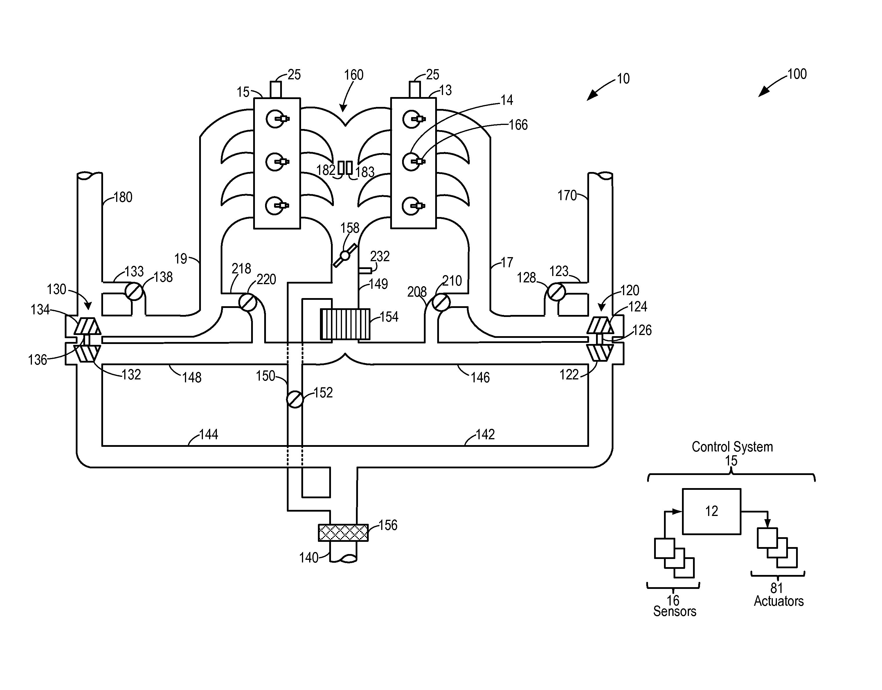
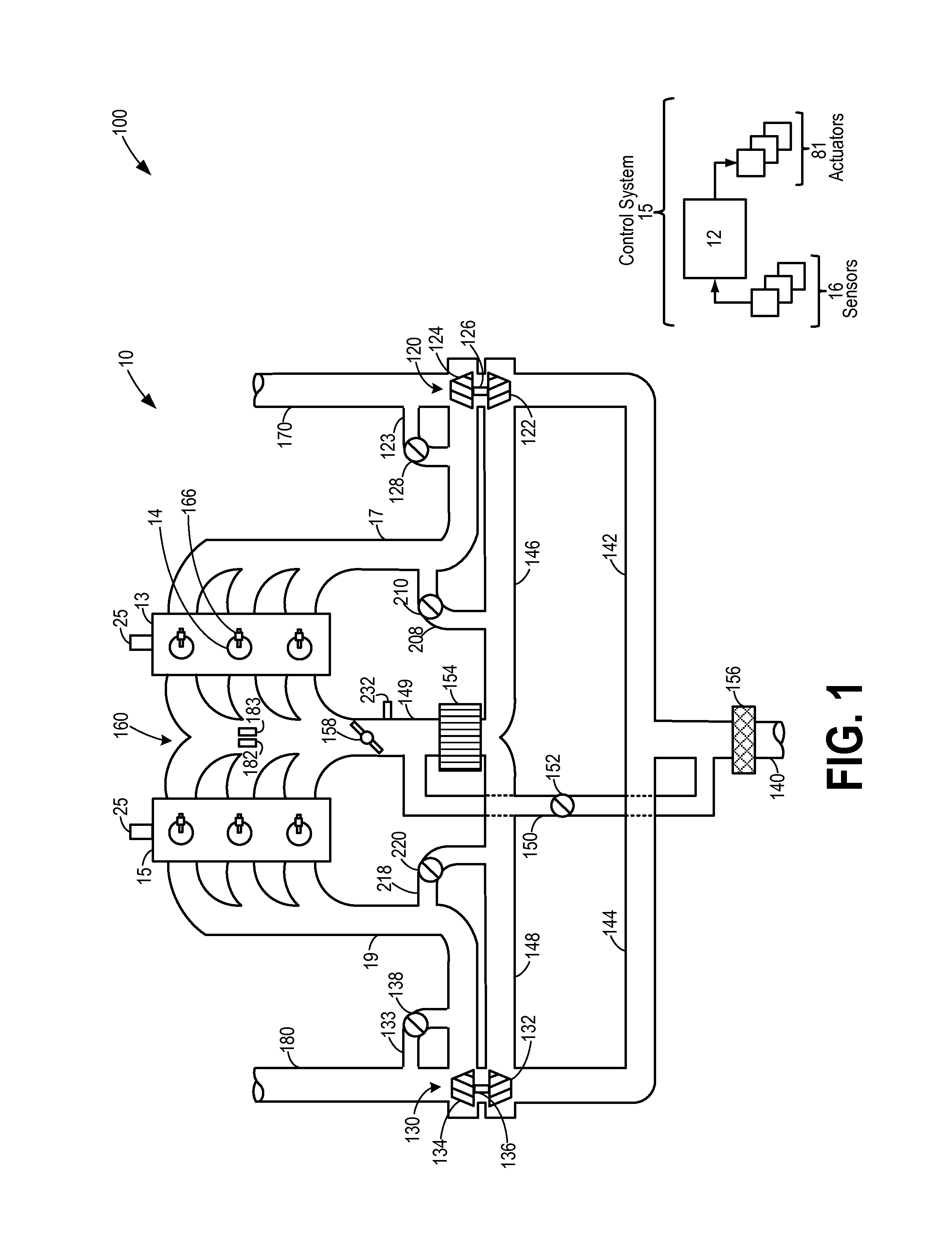
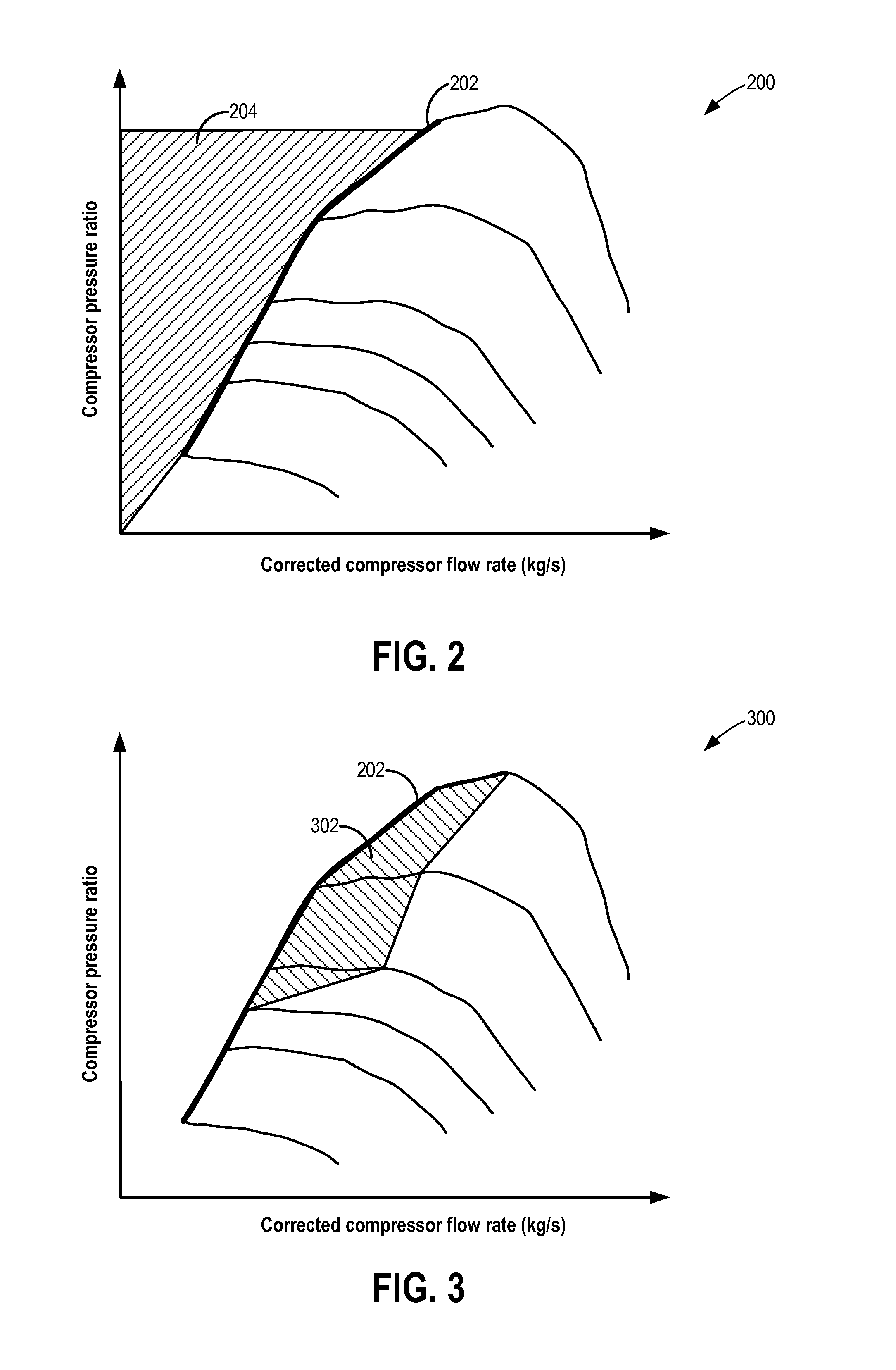
[0014]The following description relates to systems and methods for improving boost pressure control in a boosted engine system, such as the system of FIG. 1. Wastegate and compressor recirculation valve adjustments (FIG. 4) may be concurrently used to operate a turbocharger within surge limits (FIGS. 2-3). A controller may be configured to perform a control routine, such as the routine of FIG. 5, to perform feed-forward and feedback adjustments to the position of a wastegate and a compressor recirculation valve to accurately provide a boosted pressure and meet a boosted torque demand. The controller may also adjust the position of an intake throttle to compensate for air flow errors resulting from the wastegate and / or recirculation valve adjustments. The controller may also adjust a gain function of the wastegate based on the functionality of the compressor recirculation valve to further improve boost delivery time and precision. An example adjustment is shown with reference to FIG....


PUM


Abstract

Methods and systems are provided for improving boost response. A continuously variable compressor recirculation valve and a wastegate are adjusted in complementary frequency bands to move compressor operation away from a surge limit and reduce boost delivery errors. An intake throttle is also concurrently adjusted to offset manifold air-flow rate errors resulting from the wastegate or recirculation valve adjustments.

Description

FIELD[0001]The present application relates to methods and systems for coordinating wastegate actions with intake throttle and compressor recirculation valve actions to improve boost control.BACKGROUND AND SUMMARY[0002]Engine systems may be configured with boosting devices, such as turbochargers or superchargers, for providing a boosted aircharge and improving peak power outputs. The boost pressure may be regulated to a desired set-point through the actions of one or more boost actuators including, for example, a wastegate (WG) coupled across an exhaust turbine and a compressor surge valve (CSV) coupled across an intake compressor. The wastegate regulates the boost pressure by controlling the exhaust gas flow over the turbine while the compressor surge valve is commonly used for compressor surge management. Each actuator may be adjusted based on feed-forward and feedback components.[0003]As one example, wastegate adjustments affect the boost pressure through relatively slow turbochar...

Claims


Application Information

Patent Timeline
Patent Type & Authority Applications(United States)
IPC IPC(8): F02M25/07
CPCF02M25/077F02B37/16F02B37/18F02D11/10F02D23/02F02D41/0007F02D41/1401F02D2041/1409F02D2041/141F02D2200/0406F02M26/02F02M26/03Y02T10/12
Inventor JANKOVIC, MRDJAN J.BUCKLAND, JULIA HELEN
Owner FORD GLOBAL TECH LLC
Why Eureka
Try Eureka