Torque sensor arrangement and shaft comprising a torque sensor arrangement

a technology of torque sensor and arrangement, which is applied in the direction of shaft and bearing, measurement device, instruments, etc., can solve the problems of additional wear

Inactive Publication Date: 2014-09-18
SIEMENS AG
View PDF5 Cites 4 Cited by
  • Summary
  • Abstract
  • Description
  • Claims
  • Application Information

AI Technical Summary

Benefits of technology

[0010]The arrangement of the torque sensor on an electrically-operated linear carriage makes it possible to keep the distance between the torque sensor and the object to be measured, which can especially be a shaft, in a range suitable for the measurement, even if the object position varies. In this case it is not necessary to position the torque sensor on the shaft by means of a ring surrounding said shaft. It is therefore also not necessary to provide an additional roller bearing or similar on the shaft, which would lead to additional wear.
[0011]Advantageously the inventive torque sensor arrangement also includes a distance sensor, which together with the torque sensor, is disposed on the linear carriage such that it allows the measurement of the distance to the object of which the torque is to be determined. In this way it is possible to set the distance between the torque sensor and the object precisely and to detect any variations in distance that may occur and take them into account in the evaluation of the measurement signal. If a control unit is also present, which is connected to the distance sensor and is connected to the linear carriage for output of a control signal, an automatic movement towards the object with the torque sensor is made possible. The control unit in such cases determines the control signal on the basis of the distance signal output by the distance sensor, wherein the control signal represents a displacement of the torque sensor by means of the electrically-driven linear carriage by an amount which guides the torque sensor by a predetermined distance towards the object.

Problems solved by technology

It is therefore also not necessary to provide an additional roller bearing or similar on the shaft, which would lead to additional wear.

Method used


Image

  • Torque sensor arrangement and shaft comprising a torque sensor arrangement
  • Torque sensor arrangement and shaft comprising a torque sensor arrangement
  • Torque sensor arrangement and shaft comprising a torque sensor arrangement

Examples


Embodiment Construction

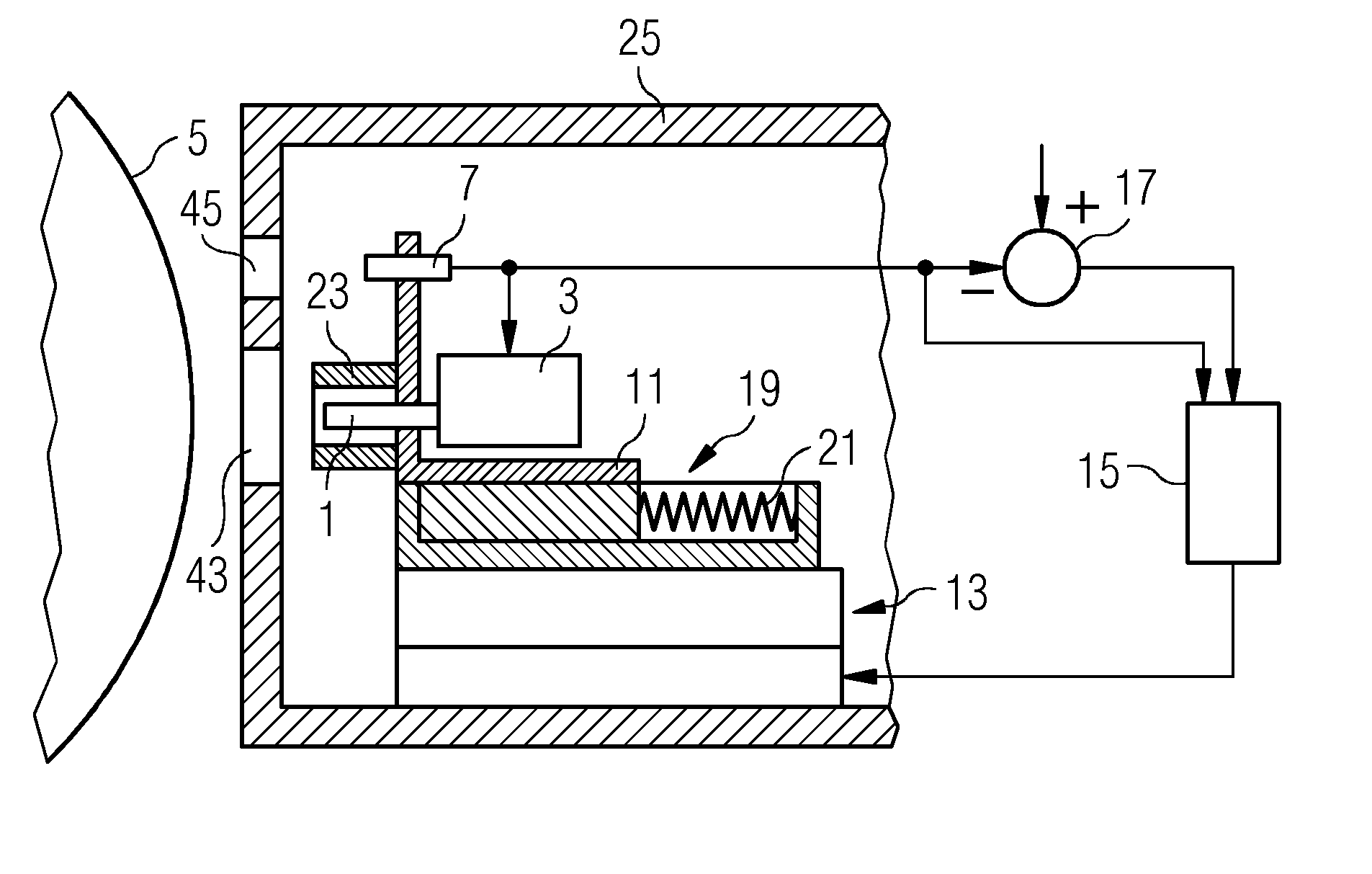
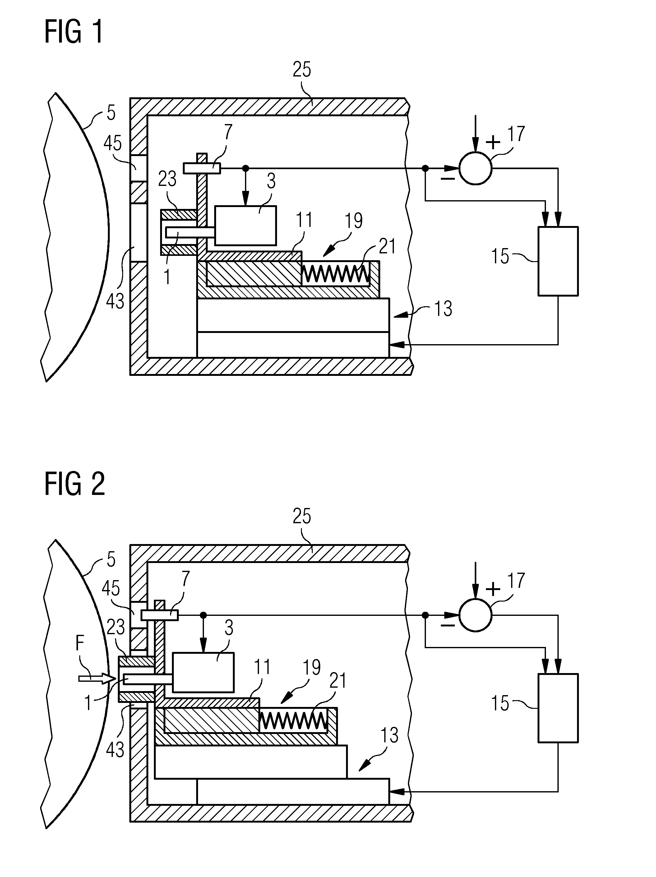
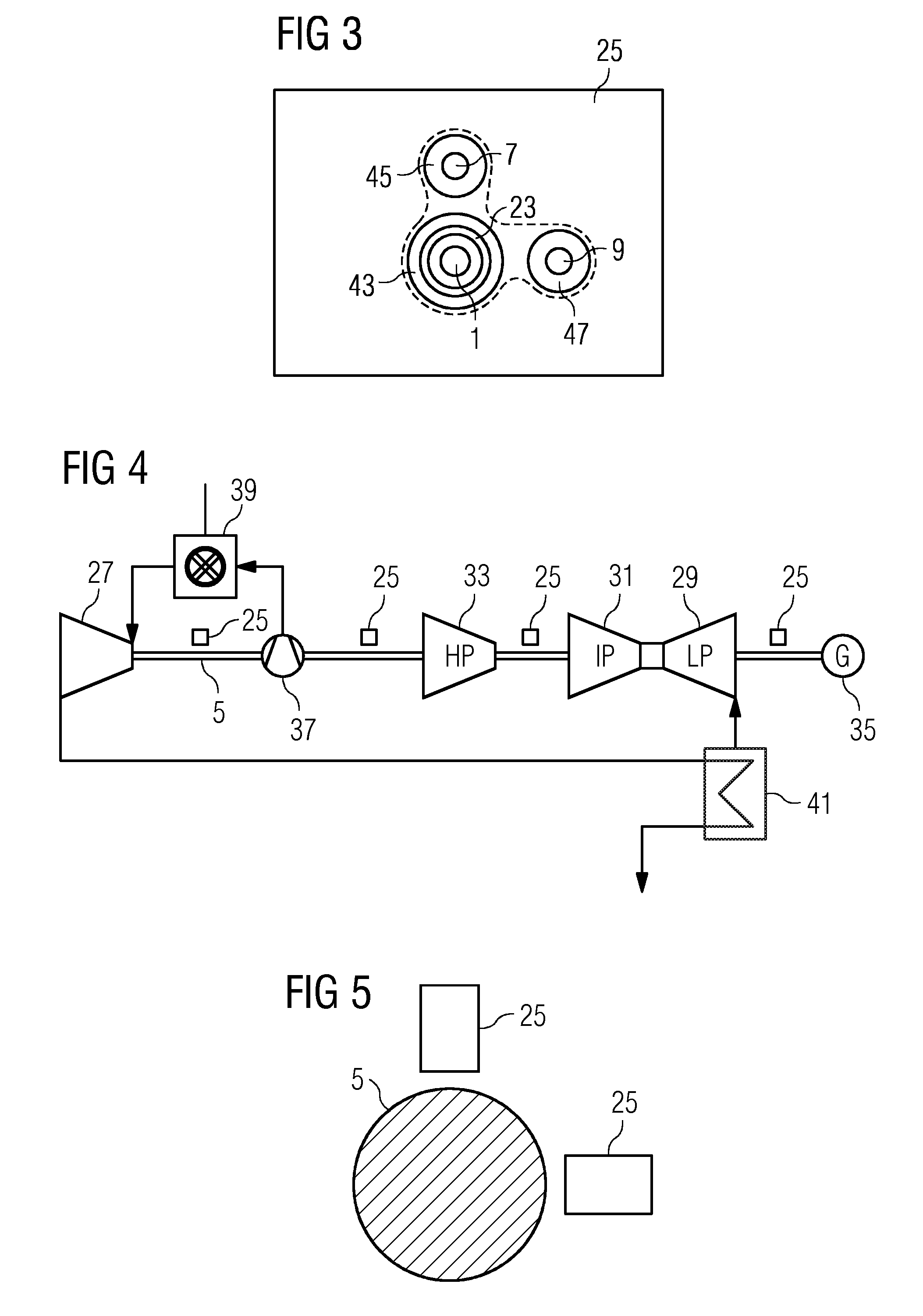
[0028]An exemplary embodiment for an inventive torque sensor arrangement will now be described below with reference to FIGS. 1 to 3. While FIG. 1 shows the torque sensor arrangement in the idle position, FIG. 2 shows the arrangement in the measurement position. FIG. 3 shows a view of the sensor arrangement from the direction of the object of which the torque is to be determined.

[0029]The inventive torque sensor arrangement comprises a torque sensor 1 which, in the present exemplary embodiment, is a magnetoelastic torque sensor. Such a sensor is based on the inverse magnetostrictive effect, i.e. the effect that ferromagnetic materials experience a change in their magnetic susceptibility when they are subjected to mechanical strains. Since mechanical strains, in addition to being induced by tensile forces and compressive forces, are also induced by torsion, the magnetostrictive effect can be employed for torque measurement, in order to measure torques of rotating objects having at lea...


PUM

PropertyMeasurementUnit
angleaaaaaaaaaa
torqueaaaaaaaaaa
distanceaaaaaaaaaa

Abstract

A torque sensor arrangement including a contactless torque sensor, in which the torque sensor is arranged on an electrically operating linear carriage is provided. A distance sensor is also arranged on the linear carriage such that it allows the distance to the object of which the torque is to be determined to be measured.

Description

CROSS REFERENCE TO RELATED APPLICATIONS[0001]This application is the US National Stage of International Application No. PCT / EP2012 / 056448 filed Apr. 10, 2012 and claims benefit thereof, the entire content of which is hereby incorporated herein by reference. The International Application claims priority to the German application No. 102011075400.8 DE filed May 6, 2011, the entire contents of which is hereby incorporated herein by reference.FIELD OF INVENTION[0002]The present invention relates to torque sensor arrangement with a torque sensor operating in a non-contact manner. In addition the invention relates to a shaft with a shaft section having a torque sensor arrangement.BACKGROUND OF INVENTION[0003]The permeability of ferromagnetic materials is influenced by mechanical strains. This physical effect, which is known as the magnetoelastic effect, can be utilized for measuring torque in a rotating object, since a torque creates strains in the rotating object. A series of different s...

Claims


Application Information

Patent Timeline
Patent Type & Authority Applications(United States)
IPC IPC(8): G01L3/10F16C3/02
CPCF16C3/02G01L3/101G01L3/102
Inventor BRUMMEL, HANS-GERDGOTZ, JURGENLINNERT, UWEMAIER, CARL UDOOSTERMAIER, JOCHEN
Owner SIEMENS AG
Why Eureka
Try Eureka