Rotary vane actuator seal

a technology of actuator seals and actuators, applied in the field of seals, can solve the problems of degrading the ability of the robotic device to remain stationary, the robotic device moving in error or not to the degree of repeatability, and the general inacceptability of the pressurized fluid to leak, so as to reduce the leak path

Inactive Publication Date: 2014-09-18
TRELLEBORG SEALING SOLUTIONS U S
View PDF4 Cites 2 Cited by
  • Summary
  • Abstract
  • Description
  • Claims
  • Application Information

AI Technical Summary

Benefits of technology

[0015]An advantage of the present invention is that a one-piece seal seals an entire chamber of a rotary vane actuator, thereby reducing leak paths.

Problems solved by technology

It is generally unacceptable for the pressurized fluid to leak.
Any leakage of fluid in the actuator may cause the robotic device to move in error or not to the degree of repeatability that is desired.
Gravitational forces acting upon the robotic arm may cause movement thereby, degrading the ability of the robotic device to remain stationary when hydraulic power is turned off.
Various attempts in the prior art have been directed at resolving the leakage issue in rotary vane actuator devices with limited success.
However, this disclosure does not address the potential leak path between the ports or the end plates.
One problem associated with prior art vane actuators is excess leakage of fluid from one side of the vane to the other, as well as leakage between the two seals on the vanes and the ends.
This prevents the actuator from maintaining the precise control over the component to be actuated or positioned.

Method used


Image

  • Rotary vane actuator seal
  • Rotary vane actuator seal
  • Rotary vane actuator seal

Examples


Embodiment Construction

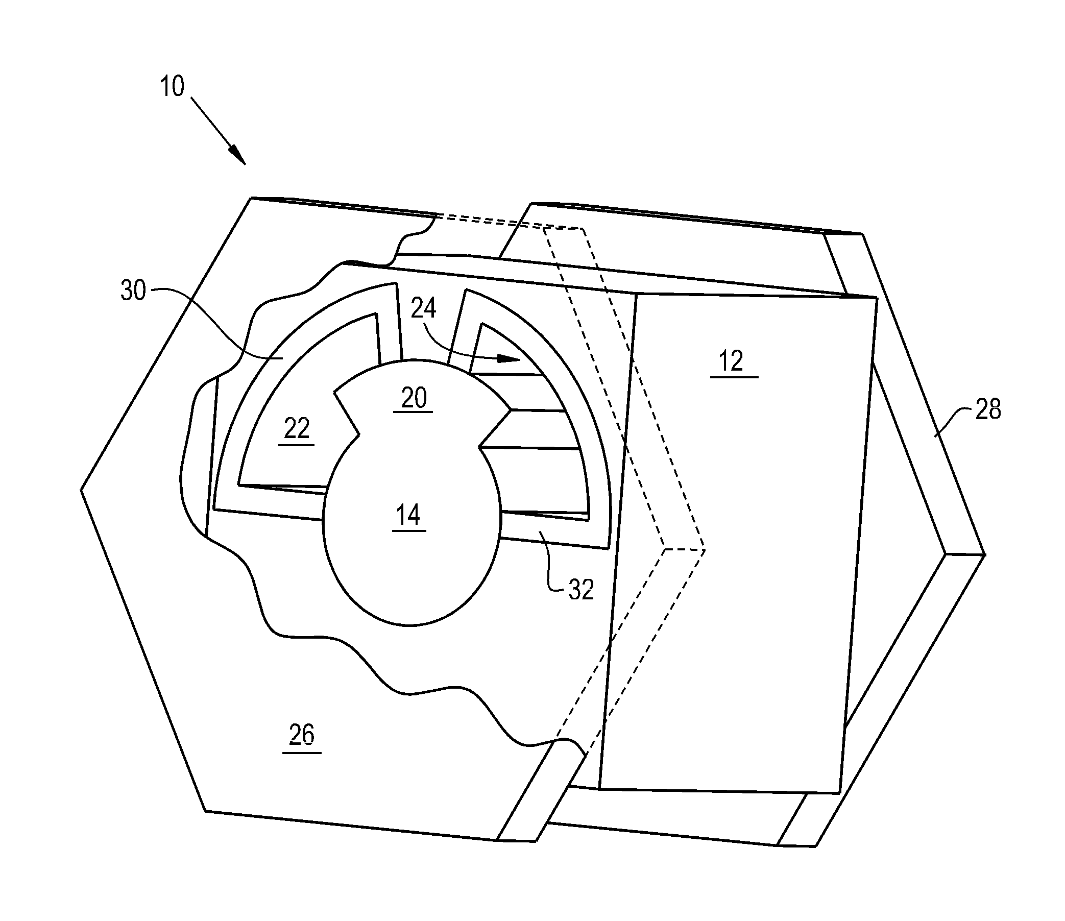
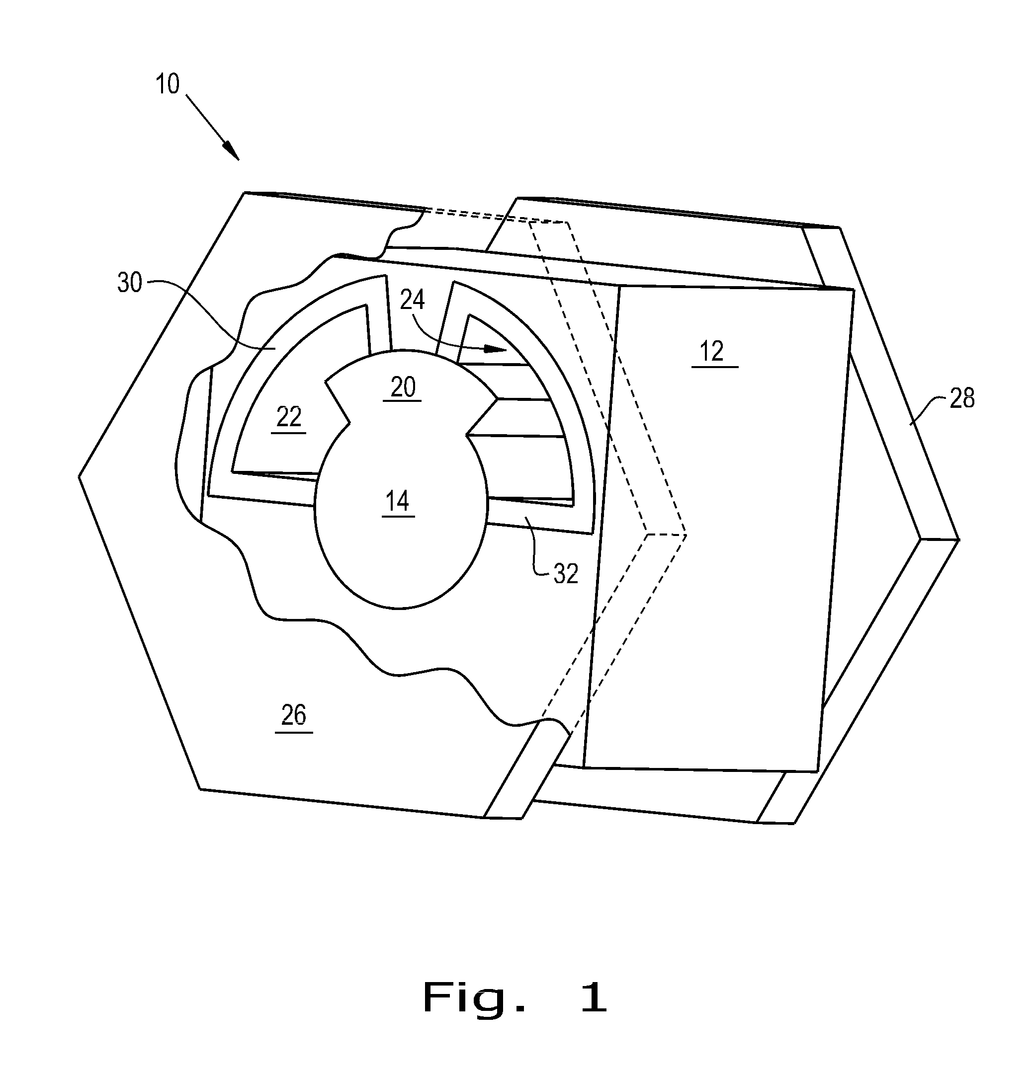
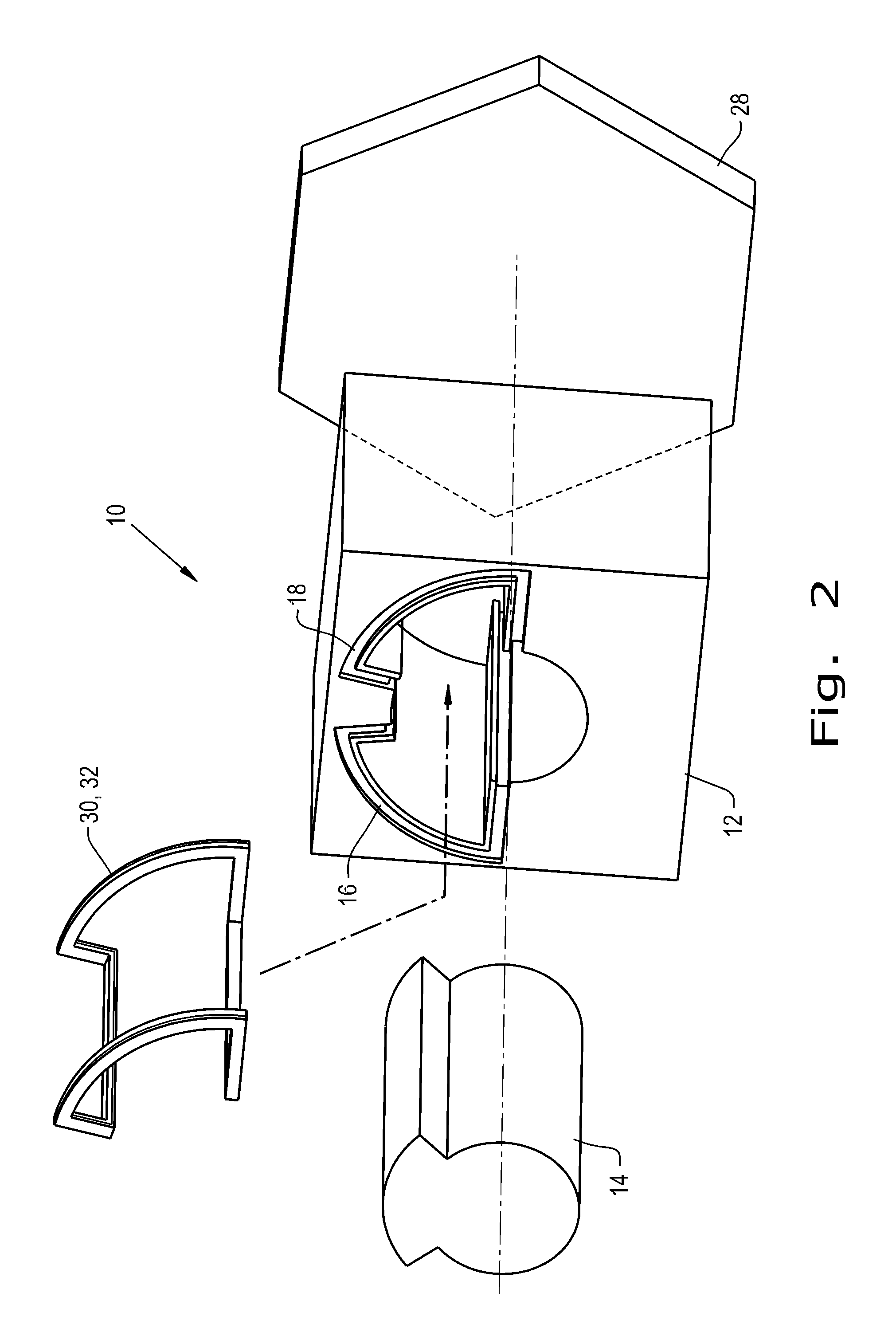
[0025]Referring now to the drawings, and more particularly to FIGS. 1 and 2, there is shown a rotary vane actuator 10 according to the present invention. The rotary vane actuator 10 includes a stator 12 and a rotor 14. Rotor 14 is situated within stator 12 such that rotational movement between stator 12 and rotor 14 takes place when pressurized fluid is introduced therebetween. Continuous stator grooves 16, and 18 exist in respective portions of stator 12 for the disposition of continuous seals 30 and 32. Ports for the controlled application and removal of fluid are not shown, for purposes of clarity. A vane 20 is an elevated portion of rotor 14. Chambers 22 and 24 are formed, with vane 20 extending into each of chambers 22 and 24. The rotational movement of vane 20 is caused by the introduction and / or removal of fluid under pressure from chambers 22 and 24, by action of valves, not shown. Likewise the rotation of vane 20 can also cause fluid to be removed or drawn into a particular...


PUM


Abstract

A sealing system for use in a rotary vane actuator having a stator and a rotor coupled to the stator. The rotor or the stator has a vane. The rotor or the stator has a groove within which the seal is positioned. The stator, the rotor and the seal coact to define a chamber. The vane being movable thereby altering a volume of the chamber, with the seal being continuous.

Description

CROSS REFERENCE TO RELATED APPLICATIONS[0001]This is a non-provisional application based upon U.S. provisional patent application Ser. No. 61 / 777,303, entitled “ROTARY VANE ACTUATOR SEAL”, filed Mar. 12, 2013, which is incorporated herein by reference.BACKGROUND OF THE INVENTION[0002]1. Field of the Invention[0003]The present invention relates to seals, and, more particularly, to a sealing system for a rotary vane actuator.[0004]2. Description of the Related Art[0005]Rotary vane actuators are used as an integral part of some robotic devices. For example, some robotic arms have multiple joints that utilize a ported rotary vane actuator. Each joint is connected to one or more ports and to a valve for moving each joint separately and / or conjunctively depending on the needed control.[0006]In order for these robotic arms to function properly, the rotor is rotated by fluid under high pressure. The fluid may be under pressures of 3000 pounds per square inch (PSI). It is generally unaccepta...

Claims


Application Information

Patent Timeline
Patent Type & Authority Applications(United States)
IPC IPC(8): B25J9/10
CPCB25J9/10B25J9/148F15B15/12
Inventor ALDAY, JENNIFER E.MOUNTZ, JOHN J.CASTLEMAN, LARRY J.
Owner TRELLEBORG SEALING SOLUTIONS U S
Why Eureka
Try Eureka