Method and device for operating an internal combustion engine

a control device and internal combustion engine technology, applied in the direction of combustion engines, electric control, machines/engines, etc., can solve the problems of unsatisfactory particulate emissions, piston standing shortly before the ignition, and close to the top dead center wet, etc., to reduce particulate emissions, reduce the effect of steady running and reducing particulate emissions

Inactive Publication Date: 2014-09-18
ROBERT BOSCH GMBH
View PDF6 Cites 0 Cited by
  • Summary
  • Abstract
  • Description
  • Claims
  • Application Information

AI Technical Summary

Benefits of technology

[0010]The method according to the present invention works on the assumption that an ignition injection quantity, which is still just sufficient to form an ignition torch, satisfies the requirement for the least possible wetting of the piston. The less the wetting of the piston, the less is the formation of soot during the combustion process, and the less the particulate emitted with the exhaust gas. Thus, the present invention achieves an optimum between reduced particulate emission and steady running of the internal combustion engine that the driver is able to perceive.
[0011]One additional embodiment of the method according to the present invention provides that the ignition injection quantity be continuously reduced until a desired pressure characteristic is achieved in the combustion chamber. In order to ensure steady running, some internal combustion engines evaluate the data of a pressure sensor situated in the combustion chamber. In this case, the ignition injection quantity may be reduced until a desired pressure characteristic sets in. In this way, steady running is ensured, and the particulate emissions are simultaneously reduced.
[0012]It is furthermore provided that the minimum actuation duration ascertained by the method according to the present invention be used for subsequent injections. The actuation duration of an actuator of the injector is proportional to the fuel quantity injected. If a minimum ignition injection quantity is ascertained, it correlates with a minimum actuation duration, as was explained before. This minimum actuation duration is stored, and subsequent injections are based on it. In this way, a high metering accuracy is ensured, especially for small injection quantities. Once the minimum actuation duration has been ascertained for one injector, the minimum ignition injection quantity for the next cylinder of the internal combustion engine is subsequently determined, or rather, the minimum actuation duration of the associated injector. The procedure according to the present invention is made possible or at least made easier by greatly restricted operating conditions during the catalytic converter heating phase. Thus, for example, the pressure in the rail is held constant and also the sequence over time of the injections is not changed, or changed only slightly during the catalytic converter heating phase.
[0013]It is additionally provided that the minimum actuation duration be continuously monitored. The monitoring of the minimum actuation duration may be done, for example, by comparing a current, newly ascertained minimum actuation duration to a value already stored. A deviation occurring in this context permits, for instance, conclusions with respect to aging effects of the injector, and may also be used to compensate for these aging effects. The deviation thus ascertained is used for calibrating the injector, and thereby increases the operating safety of the internal combustion engine.
[0014]It is particularly helpful that the sum of the fuel quantities injected in the main injection and the ignition injection is constant. In this connection, the fuel quantity injected in the ignition injection is deducted from the overall fuel quantity that is to be injected into the combustion chamber. This effectively prevents an increase in the fuel consumption by the catalytic converter heating phase.

Problems solved by technology

This fuel quantity does not contribute substantially to the torque and also does not substantially increase fuel consumption.
Besides the above desired stability of the combustion, it may also cause undesired particulate emissions.
If the partial quantity of the fuel injected to achieve the ignition torch is selected to be too small, the remaining lean mixture is not reliably ignited, and as a result it burns only incompletely.
If, on the other hand, the injection quantity is too large, the piston standing shortly before the ignition, close to its top dead center is wetted.
In this case, the result is incomplete combustion and the formation of soot particles which are exhausted along with the exhaust gas.
As a result, the catalytic converter heating phase requires great metering accuracy of small fuel quantities.
However, known methods for calibrating injectors are frequently limited in their accuracy, especially in the case of small injection quantities.

Method used


Image

  • Method and device for operating an internal combustion engine
  • Method and device for operating an internal combustion engine
  • Method and device for operating an internal combustion engine

Examples


Embodiment Construction

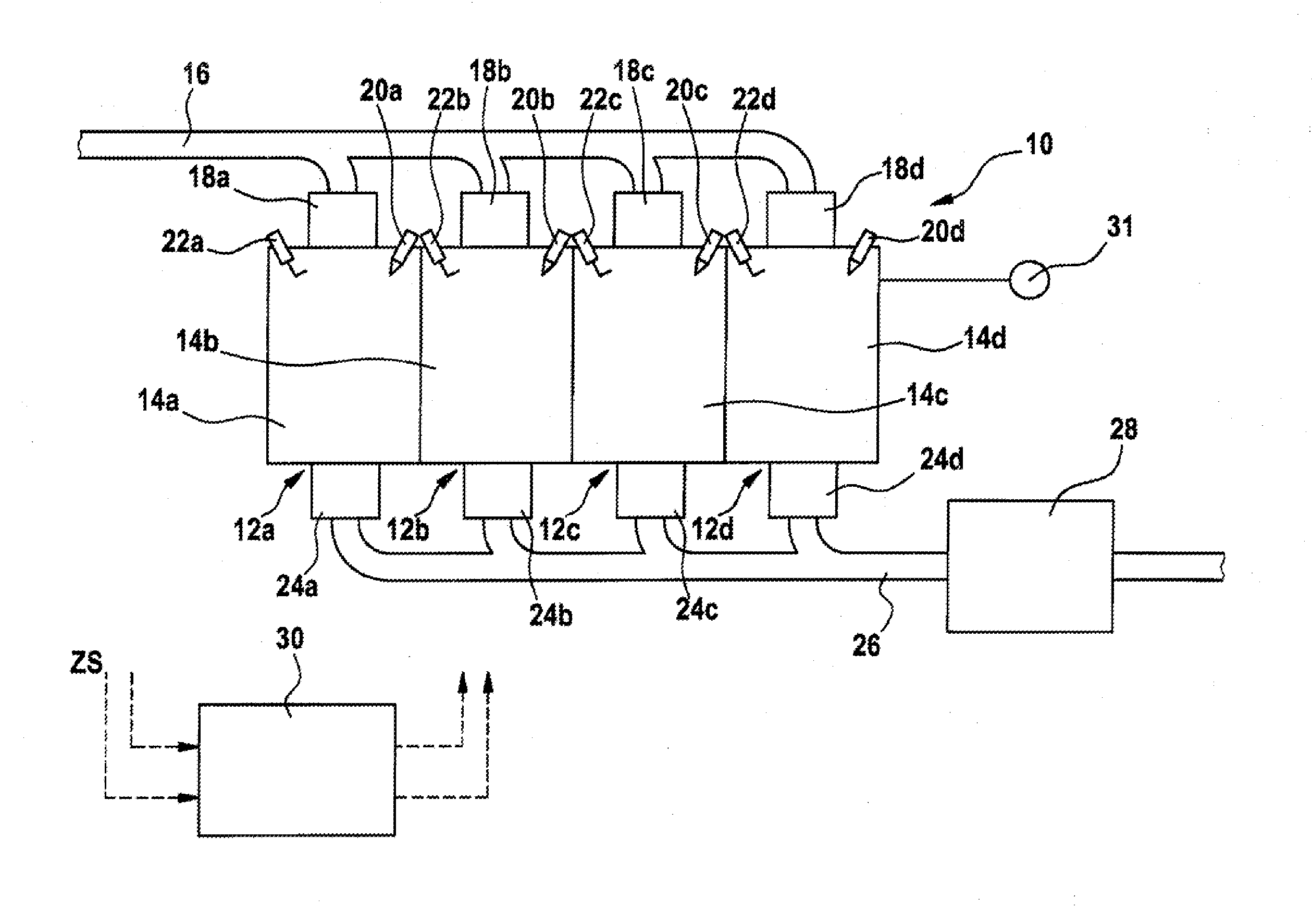
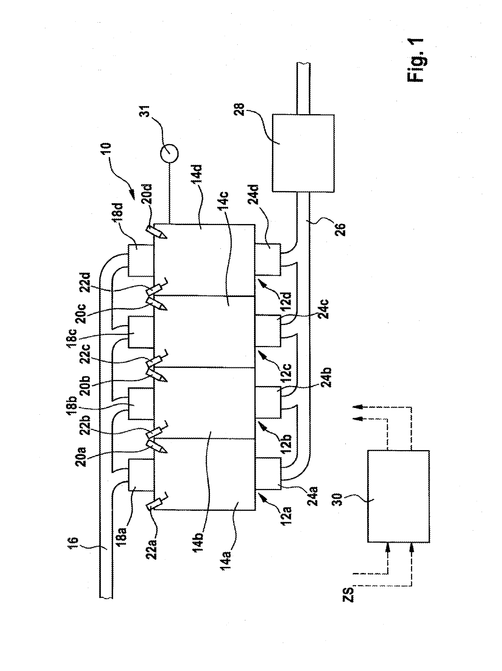
[0017]In FIG. 1, an internal combustion engine is designated overall by reference numeral 10. It is used to drive a motor vehicle, not shown, and includes four essentially identical cylinders 12a to 12d having four combustion chambers 14a to 14d. Each combustion chamber 14a to 14d has an intake valve 16a to 16d, which are connected to an intake manifold 18. Via intake manifold 18 and intake valves 16a to 16d, combustion air gets to the respective combustion chamber 14a to 14d. Fuel is injected into combustion chambers 14a to 14d via one injector 20a to 20d, respectively. Injectors 20a to 20d are connected to a rail, not shown, in which fuel is stored under high pressure.

[0018]The fuel / air mixture located in combustion chambers 14a to 14d is ignited by a spark plug 22a to 22d, respectively. The hot combustion gases are led from combustion chambers 14a to 14d into an exhaust gas pipe 26 via outlet valves 24a ro 24d. This leads to catalytic converter system 28, which purifies the exhau...


PUM


Abstract

In a method for operating an internal combustion engine during a catalytic converter heating phase, fuel in at least two portions is injected directly into at least one combustion chamber, a first portion of the fuel being injected during an intake stroke and an injection of a second portion of the fuel taking place directly before an ignition. The second portion is continuously reduced until a freely selectable boundary value of a torque fluctuation has been reached.

Description

BACKGROUND OF THE INVENTION[0001]1. Field of the Invention[0002]The present invention relates to a method and a control device for operating an internal combustion engine.[0003]2. Description of the Related Art[0004]In order rapidly to achieve the operating temperature of catalytic converters, it is known that one may heat up the catalytic converter directly after the start of the internal combustion engine, in a targeted manner, by a special injection method.[0005]An injection method is known from published German patent application document DE 10 2006 016 037 A1, in which, during a compression stroke, the fuel is introduced by at least two partial injections, the major portion of the fuel quantity being first introduced in a so-called main injection (which may also be implemented by multiple injection). Subsequently, immediately before ignition, a small portion of the fuel quantity is injected. This fuel quantity does not contribute substantially to the torque and also does not su...

Claims


Application Information

Patent Timeline
Patent Type & Authority Applications(United States)
IPC IPC(8): F02D41/30
CPCF02D41/024F02D41/247F02D41/402F02D41/30Y02T10/44Y02T10/26F02D35/023Y02T10/12Y02T10/40
Inventor JOOS, KLAUSMOESSNER, THOMASSCHLUETER, RUBENAMLER, MARKUSSTORCH, AXELWUNDERLE, MICHAELWEINMANN, MATTHIAS
Owner ROBERT BOSCH GMBH
Why Eureka
Try Eureka