Direct fuel injector

a fuel injector and direct technology, applied in the direction of fuel injection apparatus, machine/engine, feed system, etc., can solve the problems of increasing emissions, reducing combustion efficiency, and engine employing albrodt's fuel injection valve may experience wall wetting, so as to reduce fuel impingement on the cylinder walls and pistons, reduce emissions, and improve combustion efficiency

Active Publication Date: 2018-12-13
FORD GLOBAL TECH LLC
View PDF5 Cites 1 Cited by
  • Summary
  • Abstract
  • Description
  • Claims
  • Application Information

AI Technical Summary

Benefits of technology

[0003]The inventors have recognized the aforementioned problems and facing these problems developed a direct fuel injector, in one example. The direct fuel injector includes a nozzle in fluidic communication with a fuel source. The nozzle including a first set of orifices, each of the orifices in the first set arranged at a first orifice angle on an intake side of the nozzle. The direct fuel injector further includes a second set of orifices, each of the orifices in the second set arranged at a second orifice angle less than the first orifice angle on an exhaust side of the nozzle. A direct fuel injector with a first set of orifices near the intake valve having a greater orifice angle than a second set of orifices near the exhaust valve enables a spray pattern to be generated that reduces fuel impingement on the cylinder walls and piston. As a result, engines employing the direct fuel injector may achieve emission reductions and combustion efficiency gains. In particular, the spray pattern generated by the fuel injector may reduce smoke and particulate matter emissions.
[0004]As one example, the first set of orifices and the second set of orifices may each be arranged in an arc about a central axis of the nozzle and have a common vertical position with regard to a vertical axis. In this way, the injector generates a fuel spray pattern with arcing jets resembling petal shapes. This spray pattern further reduces wall wetting in the cylinder. Consequently, the engine may achieve further emissions reductions and combustion efficiency gains.

Problems solved by technology

Therefore, engines employing Albrodt's fuel injection valve may experience wall wetting.
Consequently, the fuel on the walls may not fully combust during the power stroke, thereby increasing emissions (e.g., smoke and particulate matter emissions) and reducing combustion efficiency.

Method used


Image

  • Direct fuel injector
  • Direct fuel injector
  • Direct fuel injector

Examples


Embodiment Construction

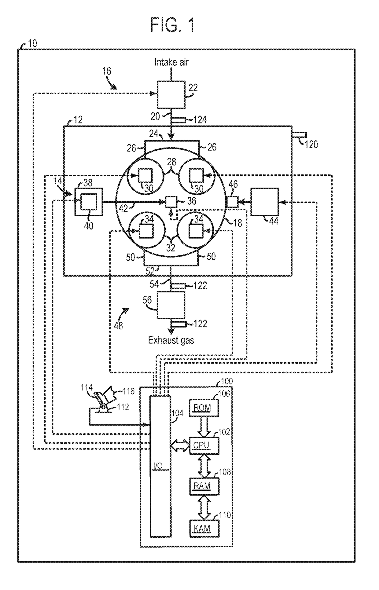
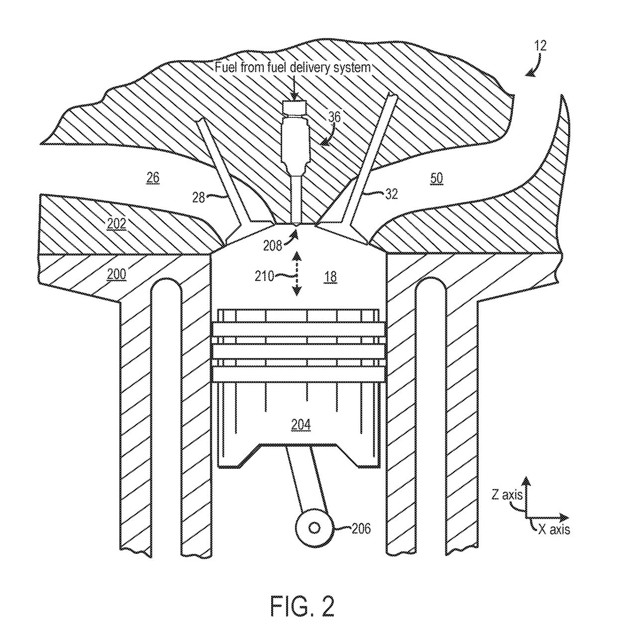
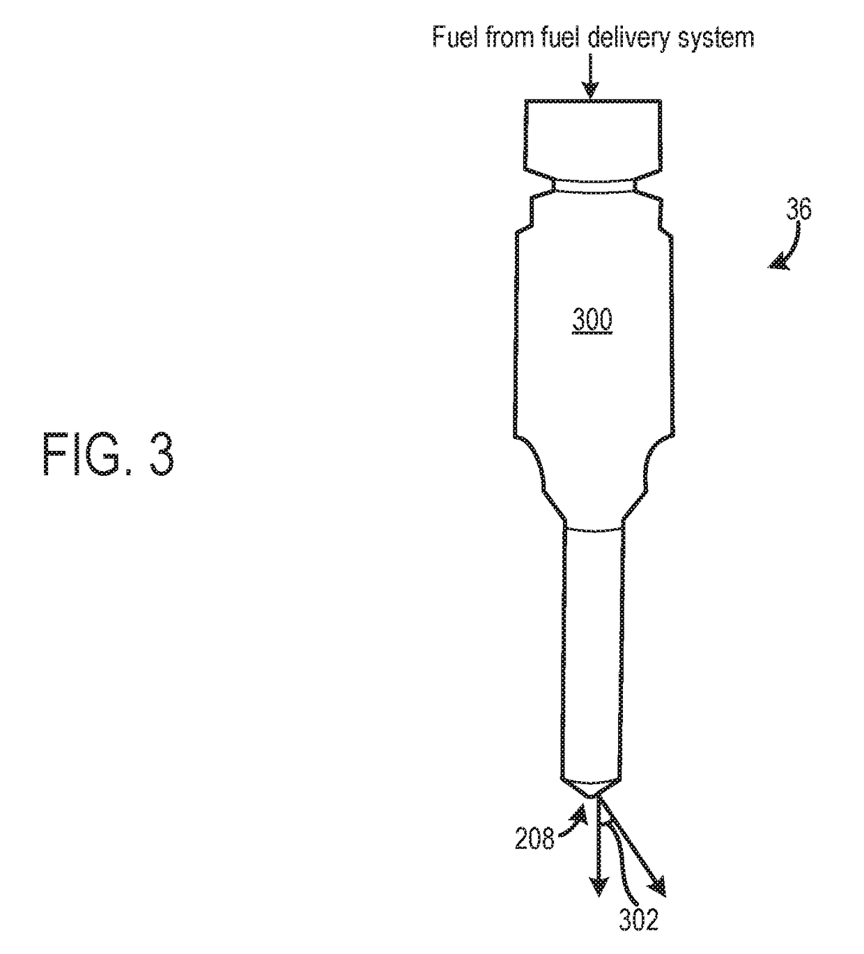
[0014]The following description relates to a direct fuel injector in a fuel delivery system of an internal combustion engine. The direct fuel injector generates a spray pattern in different arcs that decrease wall wetting. For instance, the nozzle may include different sets of orifices arranged in arcs about a central axis of the nozzle. Each of the sets of orifices may have a different theta angle (θ). Specifically, a first set of orifices adjacent to an intake valve may have a greater theta angle (θ) than a theta angle (θ) of a second set of orifices adjacent to an exhaust valve. In this way, the fuel injector nozzle generates a spray pattern resembling a petal shape that reduces wall wetting. Specifically, the smaller nozzles and the petal shaped jets generate smaller injected fuel droplets, which have less momentum when compared to previous multi-hole injectors. The reduction in momentum limits the penetration of the spray and enhances the downstream droplet dispersion in the sp...


PUM


Abstract

A fuel delivery system and a direct injector for directly injecting fuel into a cylinder are provided. In one example, a direct fuel injector includes a nozzle in fluidic communication with a fuel source, the nozzle includes a first set of orifices, each of the orifices in the first set arranged at a first orifice angle on an intake side of the nozzle. The direct fuel injector further includes a second set of orifices, each of the orifices in the second set arranged at a second orifice angle less than the first orifice angle on an exhaust side of the nozzle.

Description

FIELD[0001]The present description relates generally to a direct fuel injector in a fuel delivery system of an engine.BACKGROUND / SUMMARY[0002]Fuel delivery systems in internal combustion engines have employed fuel injectors to deliver fuel directly into engine combustion chambers. Previous direct fuel injectors have included nozzles with a small number of orifices that provide jets of fuel to combustion chambers during desired intervals. One example approach shown by Albrodt, in U.S. Pat. No. 9,194,351, is a fuel injection valve. Albrodt discloses a fuel injection valve with a perforated disk at the end of the injector valve. The perforated disk includes outlet openings configured to spray fuel in a pattern that promotes mixing. In particular, the outlet openings arrangement in Albrodt generates swirl in the fuel spray, to increase mixing in a combustion chamber. The inventors have recognized several problems with Albrodt's fuel injection valve as well as other fuel injectors. For e...

Claims


Application Information

Patent Timeline
Patent Type & Authority Applications(United States)
IPC IPC(8): F02M61/18
CPCF02M61/1813F02M61/1846F02M61/184F02M61/1826
Inventor YI, JIANWEN JAMESTING, FOO CHERNZHOU, XINLEI
Owner FORD GLOBAL TECH LLC
Why Eureka
Try Eureka